I'm starting this thread as a continuance of where this thread has gone. I have the Teensy 3.1 Serial1 RTS/CTS feature working and wanted to share my results and code changes to the Teensy core. This hardware flow control can be used as way to tame high speed serial communications between modules. Specifics for this can be found in the K20P64M72SF1RM.pdf section 47.3.14 Uart Modem Register page: 1224. I haven't tried Serial 2, 3 on the 3.1 or looked if it is possible on the Teensy LC yet. I wanted to use this as starting point on how to integrate this into the Teensy core.
To show a specific use on the teensy I have two teensy (3.1) using Serial1 at 6MHz with Teensy 1 sending to Teensy 2 as fast as possible and then sending that data to the Arduino serial monitor (Teensy 2). Without using the CTS feature on Teensy 1(sender), Teensy 2's usb can't keep up printing the received data. These examples don't use the Hardware RTS feature but a software hack because the RTS feature doesn't stall comm's for the usb. Here are two sketches and the mods to serial1.c, HardwareSerial.h and Kinetis.h:
Kinetis.h - add to
HardwareSerial.h add to "Class HardwareSerial and c implementation part"
serial1.c - add
Teensy 1 (sender) - This has the cts feature enabled.
Teensy 2 (receiver) - This uses software rts feature for stalling Teensy 1(sender) serial1 sending for usb printing (Teensy 2).
This is a pic of the setup I'm using: CTS is only available for Serial1 on pin 18 or 20 with the Teensy 3.1.

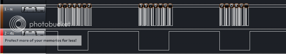
This is a pic of the data being printed to the Arduino Serial monitor without signaling Teensy 1 CTS, note: the data is not looking nice:

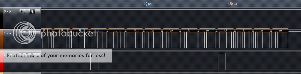
This is with CTS signaling, you can see the data looks nice now:

RTS can also be configured to replace the transmitterEnable code also but i'll talk about that later.
To show a specific use on the teensy I have two teensy (3.1) using Serial1 at 6MHz with Teensy 1 sending to Teensy 2 as fast as possible and then sending that data to the Arduino serial monitor (Teensy 2). Without using the CTS feature on Teensy 1(sender), Teensy 2's usb can't keep up printing the received data. These examples don't use the Hardware RTS feature but a software hack because the RTS feature doesn't stall comm's for the usb. Here are two sketches and the mods to serial1.c, HardwareSerial.h and Kinetis.h:
Kinetis.h - add to
Code:
[COLOR=#78492A][FONT=Menlo]#define UART0_MODEM    (KINETISK_UART0.MODEM)[COLOR=#008400]// UART Modem Register - already defined! [/COLOR][/FONT][/COLOR]
[COLOR=#78492A][FONT=Menlo]#define UART_RXRTSE     [COLOR=#272ad8]0x08[/COLOR]                 [COLOR=#008400]// Receiver request-to-send enable[/COLOR][/FONT][/COLOR]
[COLOR=#78492A][FONT=Menlo]#define UART_TXRTSPOL   [COLOR=#272ad8]0x04[/COLOR]                 [COLOR=#008400]// Transmitter request-to-send polarity[/COLOR][/FONT][/COLOR]
[COLOR=#78492A][FONT=Menlo]#define UART_TXRTSE     [COLOR=#272ad8]0x02[/COLOR]                 [COLOR=#008400]// Transmitter request-to-send enable[/COLOR][/FONT][/COLOR]
[COLOR=#78492A][FONT=Menlo]#define UART_TXCTSE     [COLOR=#272ad8]0x01[/COLOR]                 [COLOR=#008400]// Transmitter clear-to-send enable[/COLOR][/FONT][/COLOR]
HardwareSerial.h add to "Class HardwareSerial and c implementation part"
Code:
[COLOR=#008400][FONT=Menlo]// C language implementation[/FONT][/COLOR]
[FONT=Menlo][COLOR=#bb2ca2]void[/COLOR] serial_set_cts([COLOR=#703daa]uint8_t[/COLOR] pin);[/FONT]
[FONT=Menlo][COLOR=#bb2ca2]void[/COLOR] serial_set_rts([COLOR=#703daa]uint8_t[/COLOR] pin, [COLOR=#703daa]uint8_t[/COLOR] polarity);

// HardwareSerial Class[/FONT]
[FONT=Menlo][COLOR=#bb2ca2]virtual[/COLOR] [COLOR=#bb2ca2]void[/COLOR] ctsEnable(uint8_t pin) { serial_set_cts(pin); }[/FONT]
[FONT=Menlo][COLOR=#bb2ca2]virtual[/COLOR] [COLOR=#bb2ca2]void[/COLOR] rtsEnable(uint8_t pin, uint8_t polarity) { serial_set_rts(pin, polarity); }[/FONT]
serial1.c - add
Code:
[FONT=Menlo][COLOR=#bb2ca2]void[/COLOR] serial_set_cts([COLOR=#703daa]uint8_t[/COLOR] pin)[/FONT]
[FONT=Menlo]{[/FONT]
[COLOR=#78492A][FONT=Menlo][COLOR=#bb2ca2]  if[/COLOR][COLOR=#000000] (!([/COLOR]SIM_SCGC4[COLOR=#000000] & [/COLOR]SIM_SCGC4_UART0[COLOR=#000000])) [/COLOR][COLOR=#bb2ca2]return[/COLOR][COLOR=#000000];[/COLOR][/FONT][/COLOR]
[FONT=Menlo][COLOR=#bb2ca2]
 if[/COLOR] (pin == [COLOR=#272ad8]18[/COLOR]) CORE_PIN18_CONFIG = [COLOR=#78492a]PORT_PCR_MUX[/COLOR]([COLOR=#272ad8]3[/COLOR]);[/FONT]
[FONT=Menlo][COLOR=#bb2ca2]  else[/COLOR] [COLOR=#bb2ca2]if[/COLOR] (pin == [COLOR=#272ad8]20[/COLOR]) CORE_PIN20_CONFIG = [COLOR=#78492a]PORT_PCR_MUX[/COLOR]([COLOR=#272ad8]3[/COLOR]);
[/FONT][COLOR=#BB2CA2][FONT=Menlo]  else return[COLOR=#000000];[/COLOR][/FONT][/COLOR]
[COLOR=#78492A][FONT=Menlo] UART0_MODEM[COLOR=#000000] = [/COLOR]UART0_MODEM[COLOR=#000000] | [/COLOR]UART_TXCTSE[COLOR=#000000];[/COLOR][/FONT][/COLOR]
[FONT=Menlo]}[/FONT]
[FONT=Menlo]
[/FONT]
[FONT=Menlo][COLOR=#bb2ca2]void[/COLOR] serial_set_rts([COLOR=#703daa]uint8_t[/COLOR] pin, [COLOR=#703daa]uint8_t[/COLOR] polarity)[/FONT]
[FONT=Menlo]{
[/FONT][COLOR=#78492A][FONT=Menlo][COLOR=#bb2ca2]  if[/COLOR][COLOR=#000000] (!([/COLOR]SIM_SCGC4[COLOR=#000000] & [/COLOR]SIM_SCGC4_UART0[COLOR=#000000])) [/COLOR][COLOR=#bb2ca2]return[/COLOR][COLOR=#000000];
[/COLOR][/FONT][/COLOR][FONT=Menlo][COLOR=#bb2ca2]
 if[/COLOR] (pin == [COLOR=#272ad8]6[/COLOR]) CORE_PIN6_CONFIG = [COLOR=#78492a]PORT_PCR_MUX[/COLOR]([COLOR=#272ad8]3[/COLOR]);
[/FONT][FONT=Menlo][COLOR=#bb2ca2]  else[/COLOR] [COLOR=#bb2ca2]if[/COLOR] (pin == [COLOR=#272ad8]19[/COLOR]) CORE_PIN19_CONFIG = [COLOR=#78492a]PORT_PCR_MUX[/COLOR]([COLOR=#272ad8]3[/COLOR]);
[/FONT][COLOR=#BB2CA2][FONT=Menlo]  else return[COLOR=#000000];
[/COLOR][/FONT][/COLOR][COLOR=#bb2ca2][COLOR=#78492A][FONT=Menlo]
 if[/FONT][/COLOR][/COLOR][COLOR=#000000][COLOR=#78492A][FONT=Menlo] (polarity == [/FONT][/COLOR][/COLOR][FONT=Menlo][COLOR=#78492a]HIGH[/COLOR][/FONT][COLOR=#000000][COLOR=#78492A][FONT=Menlo]) [/FONT][/COLOR][/COLOR][FONT=Menlo][COLOR=#78492a]UART0_MODEM[/COLOR][/FONT][COLOR=#000000][COLOR=#78492A][FONT=Menlo] = [/FONT][/COLOR][/COLOR][FONT=Menlo][COLOR=#78492a]UART0_MODEM[/COLOR][/FONT][COLOR=#000000][COLOR=#78492A][FONT=Menlo] | [/FONT][/COLOR][/COLOR][FONT=Menlo][COLOR=#78492a]UART_TXRTSPOL[/COLOR][/FONT][COLOR=#000000][COLOR=#78492A][FONT=Menlo] | [/FONT][/COLOR][/COLOR][FONT=Menlo][COLOR=#78492a]UART_RXRTSE[/COLOR][/FONT][COLOR=#000000][COLOR=#78492A][FONT=Menlo];[/FONT][/COLOR][/COLOR][COLOR=#008400][COLOR=#78492A][FONT=Menlo]//UART_TXRTSE;
[/FONT][/COLOR][/COLOR][COLOR=#bb2ca2][COLOR=#78492A][FONT=Menlo]  else [/FONT][/COLOR][/COLOR][FONT=Menlo][COLOR=#78492a]UART0_MODEM[/COLOR][/FONT][COLOR=#000000][COLOR=#78492A][FONT=Menlo] = [/FONT][/COLOR][/COLOR][FONT=Menlo][COLOR=#78492a]UART0_MODEM[/COLOR][/FONT][COLOR=#000000][COLOR=#78492A][FONT=Menlo] | [/FONT][/COLOR][/COLOR][FONT=Menlo][COLOR=#78492a]UART_RXRTSE[/COLOR][/FONT][COLOR=#000000][COLOR=#78492A][FONT=Menlo];[/FONT][/COLOR][/COLOR]
[COLOR=#008400][FONT=Menlo]  //else UART0_MODEM = UART0_MODEM | UART_TXRTSE;[/FONT][/COLOR]
[FONT=Menlo]}[/FONT]
Teensy 1 (sender) - This has the cts feature enabled.
Code:
#define HWSERIAL Serial1
char data[1000];
char character = 0x41;


void setup() {
  pinMode(LED_BUILTIN, OUTPUT);
  memset(data, character, 998);
  data[998] = '\n';
  HWSERIAL.begin(6000000);
  HWSERIAL.ctsEnable(18);
  Serial.println("Starting High Speed Test (Sender)");
}


void loop() {
  HWSERIAL.write(data);
  //Serial.write(data);
  if (++character > 0x5A) character = 0x41;
  memset(data, character, 998);
  data[998] = '\n';
  //delay(100);
}
Teensy 2 (receiver) - This uses software rts feature for stalling Teensy 1(sender) serial1 sending for usb printing (Teensy 2).
Code:
#define HWSERIAL Serial1
#define SOFT_RTS 19 // Using as a software rts signal


void setup() {
  pinMode(LED_BUILTIN, OUTPUT);
  pinMode(SOFT_RTS, OUTPUT);
  digitalWriteFast(SOFT_RTS, HIGH);
  while(!Serial);
  delay(200);
  HWSERIAL.begin(6000000);
  Serial.println("Starting High Speed Test (Receiver)");
  digitalWriteFast(SOFT_RTS, LOW);
}


void loop() {
  if (HWSERIAL.available() > 0) {
    char buffer[64];
    int bytes = HWSERIAL.readBytesUntil(0xFF, buffer, 64);
    digitalWriteFast(SOFT_RTS, HIGH);// comment out to not use software rts
    Serial.write(buffer, bytes);
    digitalWriteFast(SOFT_RTS, LOW);// comment out to not use software rts
  }
}
This is a pic of the setup I'm using: CTS is only available for Serial1 on pin 18 or 20 with the Teensy 3.1.
This is a pic of the data being printed to the Arduino Serial monitor without signaling Teensy 1 CTS, note: the data is not looking nice:
This is with CTS signaling, you can see the data looks nice now:
RTS can also be configured to replace the transmitterEnable code also but i'll talk about that later.
")