Bat Detector - 96khz sample, FFT and iFFT?

Status
Not open for further replies.
This is close but still not correct
There is one scaling too much
after ifft the data is divided by 256, the fft size

Anyone a suggestion what to do?
multiplying output by FFT_SIZE seems a bad option.
multiplying spectra by 256 may overflow the 16 bit

I knew, it MUST be correct but I could not understand it
maybe this is all what fixed point FFT can do

according to FFT source code:

Code:
  /* output is in 11.5(q5) format for the 1024 point */
  /* output is in 9.7(q7) format for the 256 point   */
  /* output is in 7.9(q9) format for the 64 point  */
  /* output is in 5.11(q11) format for the 16 point  */

So my interpretation is that fixed point FFT looses digital resolution
1.15 becomes 11.5 for 1024 point FFT (equiv. to right shift of 10)
etc.

So lessons learned:
multiply after IFFT with fft size and
If you do not need spectral resolution make shortest FFT possible
 
Last edited:
[ Edit: Sorry, just found this thread which I need to read... https://forum.pjrc.com/archive/index.php/t-25290.html - it might answer my questions...
Thanks. ]

I'm really struggling with the changing fixed point data types needed for arm_cfft_radix4_q15 and arm_cmplx_mag_q15.

Perhaps once you know it's obvious, but I'm totally stuck with this.
I think i've figure out the simplest shift into q15 from float_32 - since my shift << 15 matches the results the built in arm function gives.

The output from q15_


As WMXZ, you can take the output of the q15 FFT, put it back through the iFFT, divide by FFT_SIZE and get back to where you started -
but I cannot figure out the inputs or outputs for arm_cmplx_mag_q15.

The documentation suggests it take 1.15 data, but if I'm doing a 256 FFT, I think I have 9.7 data.
I think the 1024 FFT gives 1.15 data, so I should have sensible data going in to the cmplx_mag, but I still don't get data I can understand back out?

Can anyone untangle me? Thanks.


Code:
#define ARM_MATH_CM4
#include <arm_math.h>
#include <arm_common_tables.h>

// This is essentially just me testing WMXZ's example program, with the /FFT_SIZE to show we can round trip his values

int SAMPLE_RATE_HZ = 122000;             // Sample rate of the audio in hertz
int DATA_RATE_HZ = 50000;                // Produce some test data for a sin at this rate
const int FFT_SIZE = 256;              // Size of the FFT. 

const int PRINT_SIZE = 20;

float buffer_f32[FFT_SIZE*2];
short buffer_q15[FFT_SIZE*2];
short buffer_q15_mine[FFT_SIZE*2];

float magnitudes_f32[FFT_SIZE];
short magnitudes_q15[FFT_SIZE];

arm_cfft_radix4_instance_q15 fft_inst_q15;
arm_cfft_radix4_instance_q15 ifft_inst_q15;

arm_cfft_radix4_instance_f32 fft_inst_f32;
arm_cfft_radix4_instance_f32 ifft_inst_f32;

////////////////////////////////////////////////////////////////////////////////
// MAIN SKETCH FUNCTIONS
////////////////////////////////////////////////////////////////////////////////

void setup() {

	// Set up serial port.
	Serial.begin(38400);
        delay(4000);
        
        arm_cfft_radix4_init_q15(&fft_inst_q15, FFT_SIZE, 0, 1);
	arm_cfft_radix4_init_q15(&ifft_inst_q15, FFT_SIZE, 1, 1);
	
	arm_cfft_radix4_init_f32(&fft_inst_f32, FFT_SIZE, 0, 1);
	arm_cfft_radix4_init_f32(&ifft_inst_f32, FFT_SIZE, 1, 1);
}


/********************************************************
Main Loop
********************************************************/

void loop() 
{
  // Generate Synthetic data....

  Serial.println("\nMake data");   
  double khz_period = 1.0 / DATA_RATE_HZ;
  double seconds_16k = 1.0 / SAMPLE_RATE_HZ;

  for (int i=0; i < FFT_SIZE; i++)
  {      
    // I need to figure out the encoding for q15_t!
    int input = (int)( 1024 * cosf( TWO_PI * ((i * seconds_16k) / khz_period) ) );
       
     buffer_f32[ (i*2)+0 ] = (input/1024.0);
     buffer_f32[ (i*2)+1 ] = 0.0;  
   
     buffer_q15_mine[ (i*2)+0 ] = myF32ToQ15(buffer_f32[ (i*2)+0 ]);
     buffer_q15_mine[ (i*2)+1 ] = myF32ToQ15(buffer_f32[ (i*2)+1 ]); 
   
  }
  
  // Fill buffer_f32 using arm conversion function...
  arm_float_to_q15(&buffer_f32[0],&buffer_q15[0],FFT_SIZE*2);
  
  Serial.println("F32 input data:");
  PrintF32Buffer(buffer_f32); // Print input data F23
  Serial.println("arm converted q15 input data:");
  PrintQ15Buffer(buffer_q15); //Print the input data Q15
  Serial.println("my converted q15 input data:");
  PrintQ15Buffer(buffer_q15_mine); //Print the input data Q15
  
  delay(4000);
  PitchShiftBuffer();
  delay(10000);
	
}

q15_t myF32ToQ15(float32_t floatVal)
{
    q15_t q15Val = (1<<15)*(floatVal);
    if (floatVal == 1.0)
    {
      q15Val = 32767;
    }
    return q15Val;
}


void PitchShiftBuffer()
{     
        // Run FFT on F32 data.
	arm_cfft_radix4_f32( &fft_inst_f32,  buffer_f32);	
        Serial.println("F32 complex FFT data:");
        PrintComplexF32Buffer(buffer_f32);// Print FFT complex data

        // Run FFT on Q15 data.
        arm_cfft_radix4_q15(&fft_inst_q15, buffer_q15);
        // the output of arm_cfft_radix4_q15 is def. not in q15 - is it in 9.7? https://www.keil.com/pack/doc/CMSIS/DSP/html/group___complex_f_f_t.html#ga8d66cdac41b8bf6cefdb895456eee84a
        Serial.println("Q15 complex FFT data:");
        PrintQ15ComplexBuffer(buffer_q15);

        // Calculate magnitude of complex f32 numbers output by the FFT.
        arm_cmplx_mag_f32(buffer_f32, magnitudes_f32, FFT_SIZE);
        Serial.println("F32 magnitude data:");
        PrintF32Magnitudes(magnitudes_f32);
        
         // Calculate magnitude of complex q15 numbers output by the FFT.
        arm_cmplx_mag_q15(buffer_q15, magnitudes_q15, FFT_SIZE);
        // The function implement 1.15 * 1.15 multiplication, finally output is converted into 2.14 format? https://www.keil.com/pack/doc/CMSIS/DSP/html/group__cmplx__mag.html#ga0a4a8f77a6a51d9b3f3b9d729f85b7a4
        Serial.println("q15 magnitude data:");
        PrintQ15Magnitudes(magnitudes_q15);

}


void PrintQ15ComplexBuffer(short *buffer)
{
  for (int i=0; i < (PRINT_SIZE); i++)
  {  
    Serial.print(buffer[i*2]); 
    Serial.print(","); 
    Serial.print( buffer[(i*2)+1]); 
    Serial.print(","); 
  }
  Serial.println("");
}

void PrintF32Buffer(float* bufferInF32)
{
  for (int i=0; i < (PRINT_SIZE); i++)
  {  
    Serial.print( bufferInF32[i*2]); 
    Serial.print(","); 
  }
  Serial.println("");
}

void PrintQ15Magnitudes(short *q15)
{
  for (int i=0; i < (PRINT_SIZE); i++)
  {  
    Serial.print(q15[i]); 
    Serial.print(","); 
  }
  Serial.println("");
}


void PrintF32Magnitudes(float* m32)
{
  for (int i=0; i < (PRINT_SIZE); i++)
  {  
    Serial.print( m32[i]); 
    Serial.print(","); 
  }
  Serial.println("");
}

void PrintComplexF32Buffer(float* bufferInF32)
{
  for (int i=0; i < (PRINT_SIZE); i++)
  {  
    Serial.print( bufferInF32[i*2]); 
    Serial.print(",");
    Serial.print( bufferInF32[(i*2)+1]); 
    Serial.print(","); 
  }
  Serial.println("");
}

void PrintQ15Buffer(short *buffer)
{
  for (int i=0; i < (PRINT_SIZE); i++)
  {  
    Serial.print(buffer[i*2]); 
    Serial.print(","); 
  }
  Serial.println("");
}

void PrintQ15BufferTimesFFT_SIZE(short *buffer)
{
  for (int i=0; i < (PRINT_SIZE); i++)
  {  
    Serial.print(buffer[i*2]*FFT_SIZE); 
    Serial.print(","); 
  }
  Serial.println("");
}
 
Last edited:
As WMXZ, you can take the output of the q15 FFT, put it back through the iFFT, divide by FFT_SIZE and get back to where you started -
Now, I don't get it
could you take my code again and modify it so that the output array is equal to input array?
(no fft_f32, and no magnitude operation)
could you then also post the printed data?

In my program the output values are already so small that division by 256 but them to zero.

Note on using floats:
your ADC will give you shorts and IMO it does make little sense to convert to float then to integer for FFT and back to float.
your DAC will also require shorts
 
Hi WMXZ - I took a diversion into magnitudes, which was a mistake.

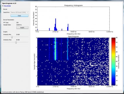
The original application I'm adapting uses the magnitudes of a f32 FFT to drive a really nice visual spectrogram.
So, I attempted to take what you'd shown me, and convert the spectrogram to be driven by q15 fft magnitudes.
That way I could check I was converting numbers from the ADC (not just test data) into q15 correctly for the FFT, and then get the magnitudes to drive the spectrogram so I could see I was getting the right answer.

Anyway, 24 frustrating hours later, I've established that the arm function to get the q15 magnitudes doesn't behave. In Paul Stoffregen's Audio library he's coded around this by implementing his own calculations to get the magnitudes. Once I borrowed those, I finally got the application working.

It was all a bit of a wild goose chase in the end. (Enough geese, time for more bats...)

spectrogram_q15.jpg
 
your ADC will give you shorts and IMO it does make little sense to convert to float then to integer for FFT and back to float.
your DAC will also require shorts

1) Does the ADC will return 2 unsigned or a signed bytes?

2) A couple of days ago you suggested that it could "be improved a little bit by not reflecting the frequencies but by setting negative frequencies to zero (analytic extension)" - can you explain that to me again?

Thanks
 
2) A couple of days ago you suggested that it could "be improved a little bit by not reflecting the frequencies but by setting negative frequencies to zero (analytic extension)" - can you explain that to me again?

Thanks

on your 2nd question
I hope I get it right without looking up textbooks

take Y=fft(X)
If you take as input a real signal ( X = sin or cos )
you get a spectrum that is symmetric in the real part (pos/neg frequencies) re(Y(N-n))= re(Y((n))
and antisymetric in the imaginary part im(Y(N-n)) = -im(Y(n)) for n>0

If you take a complex signal (X= cos + i*sin) you get a spectrum that has all negative frequencies zero n>N/2

You can try it, say with Matlab

So, an IFFT with negative frequencies set to zero results in a complex time series where the real part is the desired real time series and the imaginary part is the real time series shifted by 90 degree (is Hilbert transform of real part) (I ignore here some necessary scaling to be correct)

so, you do not have to reflect positive frequencies (lower half) to negative frequencies (upper half)
that is, setting all frequencies above (n =N/4 to N-1) to zero will result in a complex time series where the real part is the time series of interest

OT: If you were to take the absolute value of the complex time series Z=sqrt(Re(Y)^2+im(Y)^2) you get the envelope of the time series, The angle between re(Y) and im(Y) is further related to the instantaneous frequency if the signal.

BTW in for original formula you must invert imaginary part as below

Code:
for (i=1, j=N-2; i < N_on_2; i++, j--)
	{
		bufferToShiftPtr[(j*2)+0] = bufferToShiftPtr[(i*2)+0];
		bufferToShiftPtr[(j*2)+1] = - bufferToShiftPtr[(i*2)+1];
	}

edit:
The proper procedure to use this technique (FFT based analytical extension) is
- multiply positive frequencies by 2
- put all negative frequencies to zero
- keep DC part as original (or put to zero to remove DC offset)
 
Last edited:
Ok - so in the process of double checking everything - I think my microphone might be damaged.
It seems to register either almost nothing, or clipping.

I have at one point had the Audio Mono Pass Thru example working - and it no longer does.
I have a headphone setup from the DAC pin. That works nicely for the Audio sample player example.

So I took the teensy out of the equation, and connected the amp output directly to my headphone setup.
I can hear something, but it's VERY faint and noisy.

I went back to the example adafruit microphone example, and the voltages it reports are range for 0.03 to 0.40v for me speaking into the microphone, then 2+ volts if I tap the microphone.

Interestingly, I do get enough signal for an FFT to work, and pretty well.
If I get a spectrogram showing a bat click tomorrow I will post a picture.

So, I've ordered another microphone board. If I'm wrong I can at least eliminate that as a problem.

I am still having to convert the output of the ADC to a float, and then from a float into Q15.

If analogRead() return an int v (with standard binary encoding), I think the q15 should be
(v / 1024.0) * 32768
which can possibly all be accomplished using shifts?

Can anyone put me straight on this?

Thanks.
 
Last edited:
Ok.

So, I bought a spare microphone - and it behaves exactly the same as the one I was hoping was 'broken' :-(

The passthru example doesn't work for me - I hear something, but with no fidelity.
Anyone have any suggestions of what to do when the most basic hardware test fails?

I've ordered another teensy - I can't think of what else to do :-(

The microphone should work - other people use the microphones successfully in projects, and I have two (one brand new) which behave the same
(Seem to respond to very loud noises but little else)
 
Ok.
So I have a working pitch shifter.

The problem I have now is that I am reaching a speed limit.

I have other sketches with higher sampling rates that work, so I should be able to raise the sampling rate on this well above 66Khz.
(I've got other that work well at 122Khz)

Also, I should be able to cut out a lot of display code, which I have been using for visual confirmation.

Doing either of these things seems to 'tip' my sketch over the edge. I just here a constant loud tone - maybe it's crashing, it's hard to tell.

Responses have dried up a bit (perhaps rightly...) on this thread, but maybe someone more knowledgeable than me can have a look and see if they can get me going again...

Thanks.

Code:
/* Audio Spectrum Display
 Copyright 2013 Tony DiCola (tony@tonydicola.com)

 This code is part of the guide at http://learn.adafruit.com/fft-fun-with-fourier-transforms/

  Functions borrowed from sqrt_integer.h taken from Audio Library for Teensy 3.X. The following restrictions apply
 * Audio Library for Teensy 3.X
 * Copyright (c) 2014, Paul Stoffregen, paul@pjrc.com
 *
 * Development of this audio library was funded by PJRC.COM, LLC by sales of
 * Teensy and Audio Adaptor boards.  Please support PJRC's efforts to develop
 * open source software by purchasing Teensy or other PJRC products.
 *
 * Permission is hereby granted, free of charge, to any person obtaining a copy
 * of this software and associated documentation files (the "Software"), to deal
 * in the Software without restriction, including without limitation the rights
 * to use, copy, modify, merge, publish, distribute, sublicense, and/or sell
 * copies of the Software, and to permit persons to whom the Software is
 * furnished to do so, subject to the following conditions:
 *
 * The above copyright notice, development funding notice, and this permission
 * notice shall be included in all copies or substantial portions of the Software.
 *
 * THE SOFTWARE IS PROVIDED "AS IS", WITHOUT WARRANTY OF ANY KIND, EXPRESS OR
 * IMPLIED, INCLUDING BUT NOT LIMITED TO THE WARRANTIES OF MERCHANTABILITY,
 * FITNESS FOR A PARTICULAR PURPOSE AND NONINFRINGEMENT. IN NO EVENT SHALL THE
 * AUTHORS OR COPYRIGHT HOLDERS BE LIABLE FOR ANY CLAIM, DAMAGES OR OTHER
 * LIABILITY, WHETHER IN AN ACTION OF CONTRACT, TORT OR OTHERWISE, ARISING FROM,
 * OUT OF OR IN CONNECTION WITH THE SOFTWARE OR THE USE OR OTHER DEALINGS IN
 * THE SOFTWARE.
 */

#define ARM_MATH_CM4
#include <arm_math.h>
#include <Adafruit_NeoPixel.h>
#include <stdint.h>


////////////////////////////////////////////////////////////////////////////////
// CONIFIGURATION 
// These values can be changed to alter the behavior of the spectrum display.
////////////////////////////////////////////////////////////////////////////////


int SAMPLE_RATE_HZ = 66000;             // Sample rate of the audio in hertz.
float SPECTRUM_MIN_DB = 30.0;          // Audio intensity (in decibels) that maps to low LED brightness.
float SPECTRUM_MAX_DB = 60.0;          // Audio intensity (in decibels) that maps to high LED brightness.
int LEDS_ENABLED = 1;                  // Control if the LED's should display the spectrum or not.  1 is true, 0 is false.
                                       // Useful for turning the LED display on and off with commands from the serial port.
const int FFT_SIZE = 256;              // Size of the FFT.  Realistically can only be at most 256 
                                       // without running out of memory for buffers and other state.
const int AUDIO_INPUT_PIN = 16;        // Input ADC pin for audio data.
const int ANALOG_READ_RESOLUTION = 10; // Bits of resolution for the ADC.
const int ANALOG_READ_AVERAGING = 1;  // Number of samples to average with each ADC reading.
const int POWER_LED_PIN = 13;          // Output pin for power LED (pin 13 to use Teensy 3.0's onboard LED).
const int NEO_PIXEL_PIN = 3;           // Output pin for neo pixels.
const int NEO_PIXEL_COUNT = 4;         // Number of neo pixels.  You should be able to increase this without
                                       // any other changes to the program.
const int MAX_CHARS = 65;              // Max size of the input command buffer

const int OUTPUT_RATE_HZ = 22000;             // Sample rate of the audio in hertz.
IntervalTimer outputTimer;
int outputCounter = -1;

const int TARGET_SAMPLE_KHZ = 20000;          // We want this...
const int TARGET_OUTPUT_KHZ = 4000;           // Moved onto this...
// Pitch shift values
int targetFq = 0;
int lowBin = 0;
int highBin = 0;
int binOffset = 0;
int availableBeforeMirror = 0;

////////////////////////////////////////////////////////////////////////////////
// INTERNAL STATE
// These shouldn't be modified unless you know what you're doing.
////////////////////////////////////////////////////////////////////////////////

IntervalTimer samplingTimer;
float samples[FFT_SIZE*2];
float magnitudes[FFT_SIZE];

short samplesq15[FFT_SIZE*2];
short magnitudesq15[FFT_SIZE];

int sampleCounter = 0;
bool shouldFFTNow = false;
Adafruit_NeoPixel pixels = Adafruit_NeoPixel(NEO_PIXEL_COUNT, NEO_PIXEL_PIN, NEO_GRB + NEO_KHZ800);
char commandBuffer[MAX_CHARS];
float frequencyWindow[NEO_PIXEL_COUNT+1];
float hues[NEO_PIXEL_COUNT];

arm_cfft_radix4_instance_q15 q15Fft_inst;
arm_cfft_radix4_instance_q15 q15iFft_inst;


////////////////////////////////////////////////////////////////////////////////
// MAIN SKETCH FUNCTIONS
////////////////////////////////////////////////////////////////////////////////

void setup() {
  // Set up serial port.
  Serial.begin(38400);
  
  // Set up ADC and audio input.
  pinMode(AUDIO_INPUT_PIN, INPUT);
  analogReadResolution(ANALOG_READ_RESOLUTION);
  analogReadAveraging(ANALOG_READ_AVERAGING);
  analogWriteResolution(10);
  // Turn on the power indicator LED.
  pinMode(POWER_LED_PIN, OUTPUT);
  digitalWrite(POWER_LED_PIN, HIGH);
  
  // Initialize neo pixel library and turn off the LEDs
  pixels.begin();
  pixels.show(); 
  
  // Clear the input command buffer
  memset(commandBuffer, 0, sizeof(commandBuffer));
  
  arm_cfft_radix4_init_q15(&q15Fft_inst, FFT_SIZE, 0, 1);
  arm_cfft_radix4_init_q15(&q15iFft_inst, FFT_SIZE, 1, 1);
  
   setupPitchShift();
  
  // Initialize spectrum display
  spectrumSetup();
  
  // Begin sampling audio
  samplingBegin();
}

void loop() {

  // Calculate FFT if a full sample is available.
  if (shouldFFTNow) {

    shouldFFTNow = false;
    // Run FFT on sample data.

    //arm_cfft_radix4_instance_q15 q15Fft_inst;
    //arm_cfft_radix4_init_q15(&q15Fft_inst, FFT_SIZE, 0, 1);
    
    for (int i=0; i < FFT_SIZE; i++)
    {
      int j = (i*2);
      samplesq15[j] = myF32ToQ15(samples[j] / 1024.0);
      samplesq15[j+1] = 0;
    }
    // FFT sample
    arm_cfft_radix4_q15(&q15Fft_inst, samplesq15);

     for (int i=0; i < 128; i++) {
          uint32_t tmp = *((uint32_t *)samplesq15 + i); // real & imag
          uint32_t magsq = multiply_16tx16t_add_16bx16b(tmp, tmp);
          magnitudes[i] = sqrt_uint32_approx(magsq);
          if (magnitudes[i] < 0.0)
          {
            magnitudes[i] = 0.0;
          }
	}

    pitchShift(samplesq15);

    // iFFT samples    
    arm_cfft_radix4_q15(&q15iFft_inst, samplesq15);

    outputBegin();
  
    if (LEDS_ENABLED == 1)
    {
      spectrumLoop();
    }
  
    // Restart audio sampling.
    samplingBegin();
  }
    
  // Parse any pending commands.
  parserLoop();
}

void setupPitchShift()
{
  targetFq = TARGET_OUTPUT_KHZ;//(TARGET_OUTPUT_KHZ * SAMPLE_RATE_HZ) / OUTPUT_RATE_HZ;   
  lowBin = (int)((targetFq / (float)SAMPLE_RATE_HZ) * FFT_SIZE); // 10
  highBin = (int)((TARGET_SAMPLE_KHZ / (float)SAMPLE_RATE_HZ) * FFT_SIZE); //104
  binOffset = (highBin - lowBin) * 2; // 188 (94*2)
  availableBeforeMirror = (FFT_SIZE - binOffset)-2; // (256 - 188 = 68)
}

void pitchShift(q15_t* bufferToShiftPtr)
{
  q15_t *destinationPtr = bufferToShiftPtr + 2; // Leave the first value alone...
  q15_t *sourcePtr      = destinationPtr + binOffset;
  
  for (int i=0; i < availableBeforeMirror; ++i, destinationPtr++, sourcePtr++)
  {
    // Copy down...
    destinationPtr[0] = sourcePtr[0];
  }
  
  for (int i= availableBeforeMirror; i < ((FFT_SIZE*2)-2); ++i, destinationPtr++)
  {
    // pad to 0...
    destinationPtr[0] = 0;
  }
  
}

float phase = 0.0;

// [[ Output ]]
void outputCallback() {
  analogWrite(A14, (int)samplesq15[outputCounter] );
  
  outputCounter += 2;
  if (outputCounter >= 200){//FFT_SIZE*2) {
    //digitalWrite(POWER_LED_PIN, LOW);
    outputTimer.end();
    // Restart audio sampling.
    samplingBegin();
    
  }
}


void outputBegin() {
  // Reset output buffer position and start callback at necessary rate.
  digitalWrite(POWER_LED_PIN, HIGH);
  outputCounter = 0;
  outputTimer.begin(outputCallback, 1000000/OUTPUT_RATE_HZ);
  
}


q15_t myF32ToQ15(float32_t floatVal)
{
    q15_t q15Val = (1<<15)*(floatVal);
    if (floatVal == 1.0)
    {
      q15Val = 32767;
    }
    return q15Val;
}

////////////////////////////////////////////////////////////////////////////////
// UTILITY FUNCTIONS
////////////////////////////////////////////////////////////////////////////////

// Compute the average magnitude of a target frequency window vs. all other frequencies.
void windowMean(float* magnitudes, int lowBin, int highBin, float* windowMean, float* otherMean) {
    *windowMean = 0;
    *otherMean = 0;
    // Notice the first magnitude bin is skipped because it represents the
    // average power of the signal.
    for (int i = 1; i < FFT_SIZE/2; ++i) {
      if (i >= lowBin && i <= highBin) {
        *windowMean += magnitudes[i];
      }
      else {
        *otherMean += magnitudes[i];
      }
    }
    *windowMean /= (highBin - lowBin) + 1;
    *otherMean /= (FFT_SIZE / 2 - (highBin - lowBin));
}

// Convert a frequency to the appropriate FFT bin it will fall within.
int frequencyToBin(float frequency) {
  float binFrequency = float(SAMPLE_RATE_HZ) / float(FFT_SIZE);
  return int(frequency / binFrequency);
}

// Convert from HSV values (in floating point 0 to 1.0) to RGB colors usable
// by neo pixel functions.
uint32_t pixelHSVtoRGBColor(float hue, float saturation, float value) {
  // Implemented from algorithm at http://en.wikipedia.org/wiki/HSL_and_HSV#From_HSV
  float chroma = value * saturation;
  float h1 = float(hue)/60.0;
  float x = chroma*(1.0-fabs(fmod(h1, 2.0)-1.0));
  float r = 0;
  float g = 0;
  float b = 0;
  if (h1 < 1.0) {
    r = chroma;
    g = x;
  }
  else if (h1 < 2.0) {
    r = x;
    g = chroma;
  }
  else if (h1 < 3.0) {
    g = chroma;
    b = x;
  }
  else if (h1 < 4.0) {
    g = x;
    b = chroma;
  }
  else if (h1 < 5.0) {
    r = x;
    b = chroma;
  }
  else // h1 <= 6.0
  {
    r = chroma;
    b = x;
  }
  float m = value - chroma;
  r += m;
  g += m;
  b += m;
  return pixels.Color(int(255*r), int(255*g), int(255*b));
}


////////////////////////////////////////////////////////////////////////////////
// SPECTRUM DISPLAY FUNCTIONS
///////////////////////////////////////////////////////////////////////////////

void spectrumSetup() {
  // Set the frequency window values by evenly dividing the possible frequency
  // spectrum across the number of neo pixels.
  float windowSize = (SAMPLE_RATE_HZ / 2.0) / float(NEO_PIXEL_COUNT);
  for (int i = 0; i < NEO_PIXEL_COUNT+1; ++i) {
    frequencyWindow[i] = i*windowSize;
  }
  // Evenly spread hues across all pixels.
  for (int i = 0; i < NEO_PIXEL_COUNT; ++i) {
    hues[i] = 360.0*(float(i)/float(NEO_PIXEL_COUNT-1));
  }
}

void spectrumLoop() {
  // Update each LED based on the intensity of the audio 
  // in the associated frequency window.
  float intensity, otherMean;
  for (int i = 0; i < NEO_PIXEL_COUNT; ++i) {
    windowMean(magnitudes, 
               frequencyToBin(frequencyWindow[i]),
               frequencyToBin(frequencyWindow[i+1]),
               &intensity,
               &otherMean);
    // Convert intensity to decibels.
    intensity = 20.0*log10(intensity);
    // Scale the intensity and clamp between 0 and 1.0.
    intensity -= SPECTRUM_MIN_DB;
    intensity = intensity < 0.0 ? 0.0 : intensity;
    intensity /= (SPECTRUM_MAX_DB-SPECTRUM_MIN_DB);
    intensity = intensity > 1.0 ? 1.0 : intensity;
    pixels.setPixelColor(i, pixelHSVtoRGBColor(hues[i], 1.0, intensity));
  }
  pixels.show();
}


////////////////////////////////////////////////////////////////////////////////
// SAMPLING FUNCTIONS
////////////////////////////////////////////////////////////////////////////////


void samplingCallback() {
   samples[sampleCounter] = analogRead(AUDIO_INPUT_PIN);
   
  // Complex FFT functions require a coefficient for the imaginary part of the input.
  // Since we only have real data, set this coefficient to zero.
  samples[sampleCounter+1] = 0.0;
  // Update sample buffer position and stop after the buffer is filled
  sampleCounter += 2;
  if (sampleCounter >= FFT_SIZE*2) {
    shouldFFTNow = true;
    samplingTimer.end();
  }
}

void samplingBegin() {
  // Reset sample buffer position and start callback at necessary rate.
  sampleCounter = 0;
  samplingTimer.begin(samplingCallback, 1000000/SAMPLE_RATE_HZ);
}

boolean samplingIsDone() {
  return sampleCounter >= FFT_SIZE*2;
}


////////////////////////////////////////////////////////////////////////////////
// COMMAND PARSING FUNCTIONS
// These functions allow parsing simple commands input on the serial port.
// Commands allow reading and writing variables that control the device.
//
// All commands must end with a semicolon character.
// 
// Example commands are:
// GET SAMPLE_RATE_HZ;
// - Get the sample rate of the device.
// SET SAMPLE_RATE_HZ 400;
// - Set the sample rate of the device to 400 hertz.
// 
////////////////////////////////////////////////////////////////////////////////

void parserLoop() {
  // Process any incoming characters from the serial port
  while (Serial.available() > 0) {
    char c = Serial.read();
    // Add any characters that aren't the end of a command (semicolon) to the input buffer.
    if (c != ';') {
      c = toupper(c);
      strncat(commandBuffer, &c, 1);
    }
    else
    {
      // Parse the command because an end of command token was encountered.
      parseCommand(commandBuffer);
      // Clear the input buffer
      memset(commandBuffer, 0, sizeof(commandBuffer));
    }
  }
}

// Macro used in parseCommand function to simplify parsing get and set commands for a variable
#define GET_AND_SET(variableName) \
  else if (strcmp(command, "GET " #variableName) == 0) { \
    Serial.println(variableName); \
  } \
  else if (strstr(command, "SET " #variableName " ") != NULL) { \
    variableName = (typeof(variableName)) atof(command+(sizeof("SET " #variableName " ")-1)); \
  }

void parseCommand(char* command) {
  if (strcmp(command, "GET MAGNITUDES") == 0) {
    for (int i = 0; i < FFT_SIZE; ++i) {
      Serial.println(magnitudes[i]);
    }
  }
  else if (strcmp(command, "GET SAMPLES") == 0) {
    for (int i = 0; i < FFT_SIZE*2; i+=2) {
      Serial.println(samples[i]);
    }
  }
  else if (strcmp(command, "GET FFT_SIZE") == 0) {
    Serial.println(FFT_SIZE);
  }
  GET_AND_SET(SAMPLE_RATE_HZ)
  GET_AND_SET(LEDS_ENABLED)
  GET_AND_SET(SPECTRUM_MIN_DB)
  GET_AND_SET(SPECTRUM_MAX_DB)
  
  // Update spectrum display values if sample rate was changed.
  if (strstr(command, "SET SAMPLE_RATE_HZ ") != NULL) {
    spectrumSetup();
  }


  // Turn off the LEDs if the state changed.
  if (LEDS_ENABLED == 0) {
    for (int i = 0; i < NEO_PIXEL_COUNT; ++i) {
      pixels.setPixelColor(i, 0);
    }
    pixels.show();
  }
}

#ifdef __cplusplus
extern "C" const uint16_t sqrt_integer_guess_table[];
#else
extern const uint16_t sqrt_integer_guess_table[];
#endif

inline uint32_t sqrt_uint32(uint32_t in) __attribute__((always_inline,unused));
inline uint32_t sqrt_uint32(uint32_t in)
{
	uint32_t n = sqrt_integer_guess_table[__builtin_clz(in)];
	n = ((in / n) + n) / 2;
	n = ((in / n) + n) / 2;
	n = ((in / n) + n) / 2;
	return n;
}

inline uint32_t sqrt_uint32_approx(uint32_t in) __attribute__((always_inline,unused));
inline uint32_t sqrt_uint32_approx(uint32_t in)
{
	uint32_t n = sqrt_integer_guess_table[__builtin_clz(in)];
	n = ((in / n) + n) / 2;
	n = ((in / n) + n) / 2;
	return n;
}

const uint16_t sqrt_integer_guess_table[33] = {
55109,
38968,
27555,
19484,
13778,
 9742,
 6889,
 4871,
 3445,
 2436,
 1723,
 1218,
  862,
  609,
  431,
  305,
  216,
  153,
  108,
   77,
   54,
   39,
   27,
   20,
   14,
   10,
    7,
    5,
    4,
    3,
    2,
    1,
    0
};

// computes ((a[15:0] * b[15:0]) + (a[31:16] * b[31:16]))
static inline int32_t multiply_16tx16t_add_16bx16b(uint32_t a, uint32_t b) __attribute__((always_inline, unused));
static inline int32_t multiply_16tx16t_add_16bx16b(uint32_t a, uint32_t b)
{
	int32_t out;
	asm volatile("smuad %0, %1, %2" : "=r" (out) : "r" (a), "r" (b));
	return out;
}
 
Thanks WMXZ - the problem I have is that if I comment the graphics operations, for some reason the sampling seems to stop working.
It's as if it needs throttling to avoid something bad happening. When I increase the sample rate, or make the loop tighter by commenting out the graphics, something very bad happens - but I can't figure out what.
 
It might be incidental, but a
Code:
int SAMPLE_RATE_HZ = 66666;
works ok.
Where as
Code:
int SAMPLE_RATE_HZ = 66667;
breaks it.
 
Thanks WMXZ - the problem I have is that if I comment the graphics operations, for some reason the sampling seems to stop working.
It's as if it needs throttling to avoid something bad happening. When I increase the sample rate, or make the loop tighter by commenting out the graphics, something very bad happens - but I can't figure out what.

IMO, the easiest way to understand side-effects to strip down the program to a audio version only and increase sampling rate.

Your audio-visual program di help you to see id downshift works but now it seems to block process. There must be some side-effects and the program can work but maybe only by chance.
 
Phase information from FFT

At the very least, you'll need to remove that magnitude code and double the output buffer, so you can preserve the complex output.

Has anyone done something like that?

I'm interested in getting the complex output, because I understand the imaginary part of the complex number resulting from FFT holds phase information, which I would like to have available to deduce direction from the sound source (using two microhones, but quite close together).

But I'm new to C++ and amending libraries looks like a big job for a beginner...

Thanks
Graham
Is the whole Arduino paradigm not about learning Coding and constructing new systems?
Anyhow to obtain the phase you recall that
Code:
tan(phase)=sin(phase)/cos(phase)
and note that
Code:
sin(x) equiv imag(x)
cos(x) equiv real(x)
you obtain
Code:
phase(x)=atan(imag(x)/real(x))
wherby you have to consider the 5 special cases (x=0, and the 4 quadrants)
if available use
Code:
phase(x)=atan2(imag(x),real(x))

Alternatively you could use natural logarithm
Code:
phase(x)=imag(ln(x))

You may try both and see which one is faster.

Do you have a special direction-finder in mind, where you need the phase of the FFT output?

If you wanted some direction finding code, I would need your algorithm, or at least a detailed description of the problem.
 
Since you just want to shift the frequency, you could do that directly in the data -- no FFTs needed.

For example, if you expect to hear frequencies between 50 and 60 kHz, then if you multiply the input ADC signal by a sinusoid at (say) 45 kHz, you'll get signals between 5 and 15k, and also 95..105k. You can filter the higher ones relatively easily.

To avoid aliasing, you'd need the ADC to operate at at least 2x the received signals (e.g. >> 120 kHz), and the filter would need to operate at >> 2*105k. However, the filter itself is relatively easy (just a digital low pass filter), and the DAC only needs to operate at 2x the output freq (e.g. 2x 15 kHz).

So, basically, you'd ADC the input (at say 120 kHz (higher would be much better)), multiply by a (pre-computed sinusoid) at 45 kHz (120/45 = 8/3; generate 3 cycles of 45 kHz sampled at 120 kHz (e.g. 360 deg*3/8 = 135 degree steps, just 8 samples needed), low pass filter (e.g average or just add groups of 4 successive samples), and output at 120k/4 = 30 kHz DAC sampling.

So, I've had some success - but I'm struggling with the signal to noise ratio in the FFT-based solution. (I can convince myself there is something there other than noise, but it's not very conclusive)
I think whilst my microphone does have some sensitivity above 20Khz, I suspect there is a steep drop off and the noise at <20Khz is swamping it.

My bat-window for this year (here in the UK) is almost up - so I think i'll have a last go with a heterodyning solution to see if I can get some conclusive results before moving on.

I'll try to find time this evening to code up the solution suggested here by Jp3141, and I will post a prototype sketch here if I can get something working.

Thanks all.
 
Whilst I have a plausible result, I'm fairly sure I'm doing some of these steps somewhere between slightly and very wrong...

Can I tidy the code and post it here, and perhaps people would be kind enough to tell me what I've got wrong?

Thanks.

I looked the video and found a clean signal from the mouse deterrent.
So, what is the problem?
 
Ok - so I think that video (from a couple of weeks ago) shows the limits of what I could achieve using floating point based FFT. (I could JUST make 122Khz sampling rate)

In order to perform a pitch shift, then iFFT, and output the audio, I had to crank up the performance - which meant switching to q15 (fixed point) FFT and iFFT. Combined with overclocking, this gives me the speed I need (although I have to use magic numbers for the sampling / output rates to avoid crashes, for reasons I've not gotten to the bottom of...)

The penalty for using q15 is that the transforms are much more lossy - I see a lot of speckle on the graphical output, and I can hear a lot of noise.

This is ok for the nice 'long', clean, loud chirp of the mouse deterrent - but it's very hard to know if I am hearing bat clicks or just noise.

Also, I've no way of knowing for sure if my microphone is detecting anything above ~30khz (I don't have access to an general purpose ultrasound generator).

So I figure implementing a simpler, faster, heterodyning solution might answer some of these questions.
Can I hear bat clicks?
Are they too quiet?
Is the microphone too insensitive for these frequencies?

I'd love to get the FFT working - but I'm struggling with a few too many unknowns and limited time.

Thanks everyone for all the help to-date.
 
So I figure implementing a simpler, faster, heterodyning solution might answer some of these questions.
Can I hear bat clicks?
Are they too quiet?
Is the microphone too insensitive for these frequencies?

OK,
as you have a functioning system, I would do some measurements first (following list is somewhat redundant):

determine the noise level.
estimate the signal to noise level (SNR)
determine the distance up to which you can hear the deterrent device.
Figure out from documentation (or web) what the sound source level is.

once you have background noise level, determine if it is electronics only or ambient noise:
for this you put a capacitor instead of the microphone (you may have figure out what the equivalent capacitance of the microphone is, myself, I'm clueless but would start with 1-10 nF)
if the spectrum without microphone is lower than the background noise with microphone, then you microphone is the limitation, otherwise you may improve SNR by first using the build in PGA. If you are already at max gain you need external amplification.

The goal is to have an ambient noise limited acquisition system. At that point you know how far you can hear bats, as you did test with the deterrent device. you may to have to correct the source levels from deterrent device to bat.
 
If you have one of these ultrasonic distance detectors for Arduino you can check if your microphone detects the 40 KHz ou 48 KHz chirp.
 
If you have one of these ultrasonic distance detectors for Arduino you can check if your microphone detects the 40 KHz ou 48 KHz chirp.

That's a great suggestion! :-> For £2.50 I could produce a test a signal that is actually in the bat audio range!
It's hard to find next-day parts here in the UK, but I should have one by the weekend hopefully.


WMXZ - thanks for the noise suggestions. I've not embarked on your list yet. Your earlier question caused me to go back and take stock.
Most of my 'noise' is actually coming from two places.

1) Inaccuracies in the q15 FFT/iFFT - the solution for which is to switch back to F32 (with higher overclocking)

2) 'Chugging' - because I am not double buffering or anything else clever at the moment, there is a noticeable 'click' each time I start and stop outputting a 'window' 256 samples. As I change the length of the sample window, or the output rate you can hear the frequency of the 'chug' changing.
I'm still thinking of a good (simple) way to work around this...
 
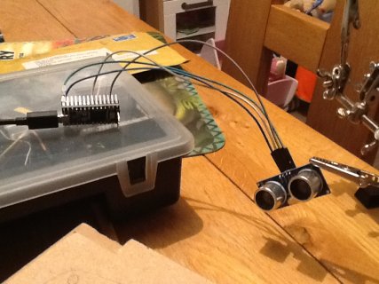
Ok. So my better fake bat arrived today - hc-sr04 ultrasonic range finder.
I have connected it up to another teensy, and it is giving me reasonable distances. (Very cool BTW).
IMG_1804.JPG

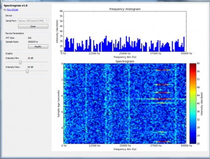
I use the ~40Khz tone to check out the sensitivity of my microphone. 120Khz is at the upper limit of the histogram program, and not all sample as visible due to the refresh/poll rate of the app. But there is a signal.noisy_bertt_screenshot.png

Using my FFT based approach, I can hear the click (sounds like one, but there should be 8 very short clicks) - but it's very faint, and if it wasn't regular I wouldn't be able to tell it from noise. Oh, and this is with the transducer at point blank...

I switched to a heterodyne approach using the following sketch
Code:
const int SAMPLE_RATE_HZ = 120000;             // Sample rate of the audio in hertz.
const int OUTPUT_RATE_HZ = 30000;             // Sample rate of the audio in hertz.
const int BUFFER_SIZE = 32;
const int AUDIO_INPUT_PIN = 16;        // Input ADC pin for audio data.
const int ANALOG_READ_RESOLUTION = 10; // Bits of resolution for the ADC.
const int ANALOG_WRITE_RESOLUTION = 12;
const int ANALOG_READ_AVERAGING = 4;  // Number of samples to average with each ADC reading.
const int POWER_LED_PIN = 13;          // Output pin for power LED (pin 13 to use Teensy 3.0's onboard LED).

IntervalTimer outputTimer;
int outputCounter = -1;

IntervalTimer samplingTimer;
float samples[ BUFFER_SIZE ];

float cannedSin[] {2048,2228.979069,1687.457902,2585.284127,1338.177732,2924.806526,1011.06964,3236.940908};

int sampleCounter = 0;
bool shouldHetrodyneNow = false;

void setup() {
  
  // Set up ADC and audio input.
  pinMode(AUDIO_INPUT_PIN, INPUT);
  analogReadResolution(ANALOG_READ_RESOLUTION);
  analogReadAveraging(ANALOG_READ_AVERAGING);
  analogWriteResolution(ANALOG_WRITE_RESOLUTION); // 0 and 4095
  // Turn on the power indicator LED.
  pinMode(POWER_LED_PIN, OUTPUT);
  digitalWrite(POWER_LED_PIN, HIGH);
 // Begin sampling audio
  samplingBegin();
}


void loop() {

  // Calculate FFT if a full sample is available.
  if (shouldHetrodyneNow) {
    shouldHetrodyneNow = false;
    heterodyning(&samples[0]);
    outputBegin();
  }
      
}

void heterodyning(float* bufferToShiftPtr)
{
  int k=0;
  for (int i=0; i < (BUFFER_SIZE/8); i++)
  {
    for (int j=0; j < 8; j++)
    {
      bufferToShiftPtr[k] = cannedSin[j] * bufferToShiftPtr[k];
      k++;
    }
  }
}


void outputCallback() {

    double avg = samples[ outputCounter] 
    + samples[ outputCounter-1]
    + samples[ outputCounter-2]
    + samples[ outputCounter-3];
    avg = avg / 4.0;

    analogWrite(A14, (int)avg);
 
    outputCounter+=4;
    
    if (outputCounter >= BUFFER_SIZE)
    {
        outputTimer.end();
        samplingBegin();        
    }
}


void outputBegin() {
  // Reset output buffer position and start callback at necessary rate.
  //digitalWrite(POWER_LED_PIN, HIGH);
  outputCounter = 3;
  outputTimer.begin(outputCallback, 1000000/OUTPUT_RATE_HZ);
  
}

////////////////////////////////////////////////////////////////////////////////
// SAMPLING FUNCTIONS
////////////////////////////////////////////////////////////////////////////////

void samplingCallback() {
   samples[sampleCounter++] = analogRead(AUDIO_INPUT_PIN) / 1024.0;
  if (sampleCounter >= BUFFER_SIZE)
  {
    shouldHetrodyneNow = true;
    samplingTimer.end();
  }
}

void samplingBegin() {
  // Reset sample buffer position and start callback at necessary rate.
  sampleCounter = 0;
  samplingTimer.begin(samplingCallback, 1000000/SAMPLE_RATE_HZ);
}
And that seems to work too, but with the same problem. Very quiet signal. (Now it really is just a click!)

I'm not really sure where to go with this now. Both approaches work, to a limited degree - but my implementations are not very effective.

Thanks to everyone for there help - but this might be one of those projects which now just gathers dust...
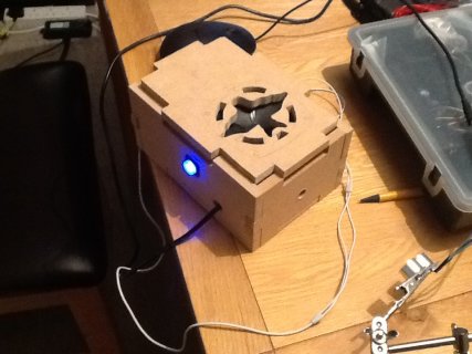
IMG_1805.JPG
 
Did you checked the microphone output with an oscilloscope? I think the ultrasonic sensor sends 4 or 8 closely spaced pulses. Looks like there is a sequence of 4 pulses on the spectrogram.
 
Did you checked the microphone output with an oscilloscope? I think the ultrasonic sensor sends 4 or 8 closely spaced pulses. Looks like there is a sequence of 4 pulses on the spectrogram.

Hi shinji - no i've not checked. I think you are correct, the range sensor emits 8 pulses - but I believe they are sufficiently close together that I'm only identifying them as a single signal on the spectrogram above (you can't see the time axis in the screenshot, but it's about 30 seconds on the vertical axis).
 
Status
Not open for further replies.
Back
Top