Bat Detector - 96khz sample, FFT and iFFT?

Status
Not open for further replies.
Audio direct into Teensy ADC? Can you get to a reasonable Nyquist rate (no matter the time- or frequency-domain signal processing with the samples)?

To me, this sounds like some fairly simple analog world processing is needed before going to a microprocessor. And the sample rate might require DMA transfers.

I wonder too if bats use swept-frequency sounds. I'd guess evolution has given them that, for best results.
 
I wonder too if bats use swept-frequency sounds. I'd guess evolution has given them that, for best results.
most bats emit FM (down sweep) echolocation signals, very often with a CW component at the beginning, where sweep rate typically changes with distance to the prey. So a combination of high range resolution and Doppler processing is very likely.

One of the puzzle, however, is that it has been demonstrated that bats do not carry out a Matched filter as done in man-made sonar (bats most likely do not store emitted signal to act as a replica, also their detection performance did not change when a time-reversed echo was played back).

Also, neuron firing rate is between 1 and 5 kHz and therefore not suited for sampling bat frequencies directly, so they have some massive parallel 'ADC' (called inner ear) that generates a huge amount of parallel low-rate pulses, that are all transmitted and processed asynchron (no epilepsy),

In other words: their bio-neural-network signal processing is still a mystery. OK, they had a long time available to train their network. Another puzzle is how thousands of echolocation bats that exit a cave can navigate without mutual interferences.

Bio-acoustics is indeed a fascinating area of research.
 
OT: to me, visual acuity of insects is amazing, e.g., honey bees and humming birds vs. the size of their brain.
 
...If the microphone can drive the capacitance of long wires, then the best approach is twin shielded cable -- this has wires inside a braided shield. Connect the shield (at one end only) to the GND of Teensy. Connect one of the other (inside) wires to GND also at the Teensy. At the microphone, connect the 2 inside wires. Do not connect the shield, unless the microphone also has a shield that is not connected to the other 2 wires....

Thanks for the advice Jp3141 - I think I understand what you're saying about the twin shielded cable.

I'm still reading through the various links above. The one WMXZ posted does explain about ground loops and noise, but I've yet to fathom exactly how that applies to the teensy when A) it's powered from a USB supply, and B) when powered from batteries (i.e, do the earth/ground characteristics change)

I also now need to wait for a shipment of parts to arrive before I can progress...

I'll post an update when the snail-mail catches up with my enthusiasm...

Thanks all.
 
Hi all,

My big bundle of bits arrived in the post yesterday, so I could finally solder up the recommended input circuit.
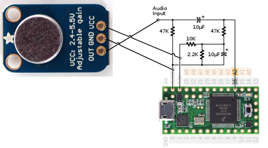
My audio source is a microphone board with a preamp, so I've wired it up as shown in the picture. (Two thirds of the picture is from the Teensy Audio Design Tool sidebar (http://www.pjrc.com/teensy/gui/?info=AudioInputAnalog)

microphone.png

Using the example File > Examples > Audio > HardwareTesting > PassThroughMono I can hear it amplifying the input, but it's VERY noisy.
I figure this could be do to one or more of the following issues:
1) The microphone isn't very good
2) I've not done a good job on the input circuit
3) I have created a ground loop

Can anyone comment on 3?
I'm making some sense of WMXZ's link above discussing ground problems - my main problem is understanding how what is discussed applies to my teensy.

Thanks.
 
Last edited:
Hi all,

My big bundle of bits arrived in the post yesterday, so I could finally solder up the recommended input circuit.
My audio source is a microphone board with a preamp, so I've wired it up as shown in the picture. (Two thirds of the picture is from the Teensy Audio Design Tool sidebar (http://www.pjrc.com/teensy/gui/?info=AudioInputAnalog)

View attachment 5061

Using the example File > Examples > Audio > HardwareTesting > PassThroughMono I can hear it amplifying the input, but it's VERY noisy.
I figure this could be do to one or more of the following issues:
1) The microphone isn't very good
2) I've not done a good job on the input circuit
3) I have created a ground loop

Can anyone comment on 3?
I'm making some sense of WMXZ's link above discussing ground problems - my main problem is understanding how what is discussed applies to my teensy.

Thanks.

IMO, if connected as per display then there should be no ground loop. If cables are short (couple of cm) then there should be no interferences.

Only issue may be that Poti on Mic should be set such that Mic output never exceeds say 0.5 V_RMS as A2 bias is set to about 0.6V.
You say very noisy. does this man without speaking to Mic?
Could you put Poti to minimum and do you still have background noise?
 
You say very noisy. does this man without speaking to Mic?
Could you put Poti to minimum and do you still have background noise?

If I turn the Poti on the Mic right down the noise gets quieter, but there is still some a pretty constant crackle.
I'm running it off 3AA batteries so the power should be pretty clean.

If I unplug the input to A2 the noise gets much louder.
 
If I turn the Poti on the Mic right down the noise gets quieter, but there is still some a pretty constant crackle.
I'm running it off 3AA batteries so the power should be pretty clean.

If I unplug the input to A2 the noise gets much louder.

If you disconnect Mic interface circuitry from A2 and you get noise then noise is due to the T3.1 alone.
Maybe some internal issues of the Audio library. As I don't use the Audio library, I'm of little help here.

Could you post the ino file (even if you only copied) so someone more knowledgeable can jump in?
You say you are using 3AA batteries (4.5V) (but not shown on schematics), did you try with USB (5V).
I would run SW without any input.
Also, what did you use to get the output? maybe the problem is there
 
Thanks for the suggestions WMXZ - I will get to your suggestions (I'm not ignoring them, you just got me thinking about the problem...)

The microphone I'm using is described as having output 2Vpp on 1.25V bias.

Now, I think that means I should expect to measure voltages of *it* of between 0.25V and 2.25V - with it 'floating' at 1.25V when there is no 'sound'...

So, i'm using the recommended input circuitry (shown in figure in previous post). Now, I don't fully understand it, but I have been assuming that the main purpose is for the capacitor to remove the DC bias.

If that's the case - maybe I'm now measuring voltages (with 1.25V removed) in the range -1V to +1V?
Clearly if the ADC is expecting to work in the range 0-2.56V then that's going to behave oddly?

Should I not be removing the DC bias?

As far as I understand, the circuitry Paul suggested and you are using to interface the Mic is indeed removing the MIC DC bias and replacing it with a 0.6V DC bias

voltage divider 10k-2.2k (3.3*2.2/12.2 = 0.6)

so your audio swing should be limited to DC+- 0.6 V
 
I am a bit curious why the voltage divider doesnt make the DC bias on the analog input to 1.65 V using 4.7k and 4.7k instead of 10k and 2.2k ?
 
I rebuilt the audio input circuit. I changed the voltage divider to 10k-10k to give 1.65V DC bias.
So I should be able to read the full +/-1V audio swing from the microphone.

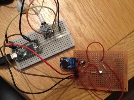
IMG_1772.JPG

Using the setup in this picture with the following sketch:
Code:
int SAMPLE_RATE_HZ = 44000;             // Sample rate of the audio in hertz.
                                       // without running out of memory for buffers and other state.
const int AUDIO_INPUT_PIN = 16;        // Input ADC pin for audio data.
const int ANALOG_READ_RESOLUTION = 8; // Bits of resolution for the ADC.
const int ANALOG_READ_AVERAGING = 4;  // Number of samples to average with each ADC reading.
const int POWER_LED_PIN = 13;          // Output pin for power LED (pin 13 to use Teensy 3.0's onboard LED).

IntervalTimer samplingTimer;

void setup() {
  // Set up serial port.
  Serial.begin(38400);
  
  // Set up ADC and audio input.
  pinMode(AUDIO_INPUT_PIN, INPUT);
  analogReadResolution(ANALOG_READ_RESOLUTION);
  analogReadAveraging(ANALOG_READ_AVERAGING);
  
  analogWriteResolution(12);
  // Turn on the power indicator LED.
  pinMode(POWER_LED_PIN, OUTPUT);
  digitalWrite(POWER_LED_PIN, HIGH);
    
  // Begin sampling audio
  samplingBegin();
  
}

void loop() {  
}

void samplingCallback() {
  // Read from the ADC and store the sample data
  int sample = analogRead(AUDIO_INPUT_PIN);
  analogWrite(A14, sample);
  //Serial.println( 3.3*(sample/1024.0) );
}

void samplingBegin() {
  samplingTimer.begin(samplingCallback, 1000000/SAMPLE_RATE_HZ);
}

I mostly hear crackle.
The gain on the mic board is set halfway up.

Interesting, I can actually hear an ultra-sonic beep. I have a small mouse deterrent which beeps loudly at 30khz - and through this setup, the beep is audible through the headphones.

What I was actually trying to do is make 'pass-through' example, where I can just here in the headphones what the microphone could hear...
Can anyone see from this where I'm going wrong?

Thanks everyone for you patience
 
I rebuilt the audio input circuit. I changed the voltage divider to 10k-10k to give 1.65V DC bias.
So I should be able to read the full +/-1V audio swing from the microphone.


I mostly hear crackle.
The gain on the mic board is set halfway up.

Interesting, I can actually hear an ultra-sonic beep. I have a small mouse deterrent which beeps loudly at 30khz - and through this setup, the beep is audible through the headphones.

What I was actually trying to do is make 'pass-through' example, where I can just here in the headphones what the microphone could hear...
Can anyone see from this where I'm going wrong?

Thanks everyone for you patience

30 kHz is definitely aliased (> 22 kHz) so you should hear an audible tone

concerning Headphone on DAC, have you seen

https://forum.pjrc.com/threads/24967-Teensy-3-1-DAC-audio-output?p=40857&viewfull=1#post40857 ?

but maybe your HW is already driving correctly the headphone, so you have to analyze input.

Thanks WMXZ.

I'm running the headphone through a 10uF capacitor, and the samplerPlayer example and a tone synth example both produce good sounds for me.

I guess as you say, my input might not be quite what I'm expecting.
I built a histogram for 50,000 samples, and the adc was producing a good spread of voltage values.
It's just frustrating that I can' them to get a sensible round trip from microphone to headphones.

If you can exclude DAC, you have to work on ADC.

Typically in such a situation, I would ignore the original application try to find a configuration that works.
So I would set ADC to lower sampling rate, higher resolution, and NO averaging (that feature is, IMO, only for measuring DC and not audio (lack of anti-aliasing filter))
In fact I would first set averaging to 1 or comment hat line.

Another aspect you have to consider is the Vref of the ADC
As I understand it, Vref is the highest Voltage you convert. T3.1 can have internal or external Vref. One (only?) known internal value is 1.2V.
According to your schematic, you are not providing Vref.
So I suggest, to set Vref to internal 1.2 V and the input bias back to 0.6V.
You can have a look into input_adc.cpp of the audio library.
 
Unless you have a speaker very close to the microphone, I doubt you are overloading it and need much more than 0.6 V DC bias.

Since you can run a histogram -- can you get the data and import into Excel and then plot it ?

If you whistle to the microphone (not too close -- say 1 m away), you should see something sort looking like a sinewave. Else get one of those sound generating apps for a smartphone and use it to create sounds. If you can only do histograms, then a squarewave should show 2 main peaks and little in between.
 
Thanks for the help everyone!

Setting the read/write resolution back to normal got me back on track... Thanks to WMXZ.

Jp3141 - The continuity check on my multimeter makes a really handy tone - thanks for the suggesting.


I took my prototype out with the bats earlier, and I can kinda convince myself there is something there behind the noise.

One problem I have with my current code is that the FFT/iFFT is proportionally slow compared to the rate I gather data.
The time taken to FFT 1024 samples is constant, but as I increase the sampling frequency, 1024 samples covers a small and smaller window of time:
hz MS sampling MS not sampling % of elapsed time spent 'listening'
22000 14332 19077 43%
44000 7507 20164 27%
88000 3796 20663 16%
96000 4242 24839 15%
100000 3498 20808 14%
120000 1576 10141 13%

Now, I can live with 13% - it's better than nothing.
The problem I have is an audible click when the buffers swap...
The cycle goes:
- 87% bg noise
- loud click
- 13% noisy data
- loud click
[repeat]

How could I go about setting up a gentle sort of pink noise sinusoid for 100% of the time, and then overlay the 'data' for the 13% of the time it's available?
(I'm listening for clicks, so clicks switching between buffers are a real pain)

Here is my current code - all comments welcome!

Code:
#define ARM_MATH_CM4
#include <arm_math.h>

// This is a branch from 29 that uses a single playback timer...

// Removed buffer C in favour of analog read
// Start 2 timers (input and output)
// Fill bufferC with background noise (FFT it, pitch shift, iFFT) - keep this to fill gaps between real data
// Gather data into bufferA and bufferB alternatly
// If a buffer is full, FFT and pitch shift it, iFFT and then start playback of that buffer.

int SAMPLE_RATE_HZ = 88000;             // Sample rate of the audio in hertz.

const int FFT_SIZE = 1024;              // Size of the FFT.  Realistically can only be at most 256 
// without running out of memory for buffers and other state.
const int AUDIO_INPUT_PIN = 16;        // Input ADC pin for audio data.
const int ANALOG_READ_RESOLUTION = 12; // Bits of resolution for the ADC.
const int ANALOG_READ_AVERAGING = 1;  // Number of samples to average with each ADC reading.
const int ANALOG_WRITE_RESOLUTION = 12;
const int POWER_LED_PIN = 13;          // Output pin for power LED (pin 13 to use Teensy 3.0's onboard LED).

long   m_loopCounter = 0;
bool   m_LEDOn = true;

bool   m_pitchShiftOn = true;

IntervalTimer bufferFillTimer;
IntervalTimer bufferEmptyTimer;

float bufferA[FFT_SIZE*2];
float bufferB[FFT_SIZE*2];

bool fillingBufferA = false;
int bufferANextPushIndex = 0;

bool fillingBufferB = false;
int bufferBNextPushIndex = 0;

bool emptyingBufferA = false;
int bufferANextPopIndex = 0;

bool emptyingBufferB = false;
int bufferBNextPopIndex = 0;

bool playFromInput = false;

////////////////////////////////////////////////////////////////////////////////
// MAIN SKETCH FUNCTIONS
////////////////////////////////////////////////////////////////////////////////

void setup() {

	// Set up serial port.
	//Serial.begin(38400);
	// Set up ADC and audio input.
	pinMode(AUDIO_INPUT_PIN, INPUT);
	analogReadResolution(ANALOG_READ_RESOLUTION);
	analogReadAveraging(ANALOG_READ_AVERAGING);
        analogReference(DEFAULT);
	analogWriteResolution(ANALOG_WRITE_RESOLUTION);
	// Turn on the power indicator LED.
	pinMode(POWER_LED_PIN, OUTPUT);
	digitalWrite(POWER_LED_PIN, HIGH);

	playFromInput = true; // Start off outputing from input (not processing) immediately
	
	bufferFillTimer.begin(  BufferFillingCallback, 1000000/SAMPLE_RATE_HZ);
	bufferEmptyTimer.begin( BufferEmptyingCallback, 1000000/SAMPLE_RATE_HZ);

	BeginFillingBufferA(); // Start collecting on buffer A (being double buffering)


}

bool BufferAIsFull() {  return bufferANextPushIndex >= (FFT_SIZE*2); }
bool BufferBIsFull() {  return bufferBNextPushIndex >= (FFT_SIZE*2); }

bool WeAreNotCurrentlyFillingBufferA() { return !fillingBufferA; }
bool WeAreNotCurrentlyFillingBufferB() { return !fillingBufferB; }

bool WeAreNotCurrentlyEmptyingBufferA() { return !emptyingBufferA; }
bool WeAreNotCurrentlyEmptyingBufferB() { return !emptyingBufferB; }

/**************************************************************
Filling Methods
**************************************************************/

void BufferFillingCallback() {
	// Data for FFT is complex pair [value,0.0]
        if (fillingBufferA)
	{
		bufferA[bufferANextPushIndex] = (float32_t)analogRead(AUDIO_INPUT_PIN);
		bufferA[bufferANextPushIndex+1] = 0.0;
		bufferANextPushIndex += 2;
		if (bufferANextPushIndex >= FFT_SIZE*2) {
			fillingBufferA = false;
		}
	}
	else if (fillingBufferB)
	{
		bufferB[bufferBNextPushIndex] = (float32_t)analogRead(AUDIO_INPUT_PIN);
		bufferB[bufferBNextPushIndex+1] = 0.0;
		bufferBNextPushIndex += 2;
		if (bufferBNextPushIndex >= FFT_SIZE*2) {
			fillingBufferB = false;
		}
	}
	
}

void BeginFillingBufferA() 
{
	fillingBufferA = true;
	bufferANextPushIndex = 0;
}

void BeginFillingBufferB() 
{
	fillingBufferB = true;
	bufferBNextPushIndex = 0;
}


/**************************************************************
Emptying Methods
**************************************************************/

void BufferEmptyingCallback() {

	if (emptyingBufferA)
	{
		digitalWrite(POWER_LED_PIN, LOW);
		analogWrite(A14, (int)bufferA[bufferBNextPopIndex]);
		bufferANextPopIndex += 2;
		if (bufferANextPopIndex >= FFT_SIZE*2) {
			emptyingBufferA = false;
			bufferANextPushIndex = 0;
			playFromInput = true;                        
		}
	}
	else if (emptyingBufferB)
	{
		digitalWrite(POWER_LED_PIN, LOW);
		analogWrite(A14, (int)bufferB[bufferBNextPopIndex]);
		bufferBNextPopIndex += 2;
		if (bufferBNextPopIndex >= FFT_SIZE*2) {
			emptyingBufferB = false;
			bufferBNextPushIndex = 0;
			playFromInput = true;
                        
		}
	}
	else 
	{
                analogWrite(A14,analogRead(AUDIO_INPUT_PIN));		
                digitalWrite(POWER_LED_PIN, HIGH);               
	}
	  
}

void BeginEmptyingBufferA() 
{
	emptyingBufferA = true;
	bufferANextPopIndex = 0;
}


void BeginEmptyingBufferB() 
{
	emptyingBufferB = true;
	bufferBNextPopIndex = 0;
}


/********************************************************
Main Loop
********************************************************/

void loop() {

	// Don't do anything if Buffer A is not yet full
	if ( BufferAIsFull() )
	{      
		// Just hold on if A is full but B is not emptying
		if ( WeAreNotCurrentlyEmptyingBufferB() )
		{
                        if ( WeAreNotCurrentlyFillingBufferB() && !BufferBIsFull() )
			{
                                // If A is full, and we are not emptying B, and not filling B, and B is not full..
  				BeginFillingBufferB(); 
			}

			if ( WeAreNotCurrentlyEmptyingBufferA() )
			{
                            // If A is full, and we are not emptying B, and not emptying A
				PitchShiftBuffer(bufferA);
				BeginEmptyingBufferA();  
			}			
		}//end not currently emptying buffer B

	}//end BufferAIsFull()

	// Don't do anything if Buffer B is not yet full
	if ( BufferBIsFull() )
	{

		// If Buffer B is full but we are processing a full buffer A, then just wait...
		if ( WeAreNotCurrentlyEmptyingBufferA() )
		{
                        if ( WeAreNotCurrentlyFillingBufferA() && !BufferAIsFull() )
			{
				// If Buffer B is full
				// And we are not emptying A
				// And A is not already full
				BeginFillingBufferA(); 
			}

			if ( WeAreNotCurrentlyEmptyingBufferB() )
			{
				// Start emptying B if
				// Buffer A is full
				// And we are not currently emptying buffer A
				// And we are not already emptying buffer B
				PitchShiftBuffer(bufferB);

				BeginEmptyingBufferB();  
			}

			
		}//end not currently emptying buffer A

	}//end BufferBIsFull()
}

void PitchShiftBuffer(float* bufferToShiftPtr)
{
  
	// Run FFT on sample data.
	arm_cfft_radix4_instance_f32 fft_inst;
	arm_cfft_radix4_init_f32(&fft_inst, FFT_SIZE, 0, 1);
	arm_cfft_radix4_f32(&fft_inst, bufferToShiftPtr);
  if (m_pitchShiftOn)
  {
	// Shift the frequency....
	pitchShift(bufferToShiftPtr);

  }
  	arm_cfft_radix4_init_f32(&fft_inst, FFT_SIZE, 1, 1);
	arm_cfft_radix4_f32(&fft_inst, bufferToShiftPtr);
  
}

void pitchShift(float* bufferToShiftPtr)
{

	int N = FFT_SIZE;
	int N_on_2 = N/2;
	int N_on_4 = N/4;

	// There are 1024 bins
	// We only care about the first 512
	// Of those, I only care about the ones from 384 to 512
        if (false)
        {
        	// Down shift second quarter onto first
        	int k=1;
        	for (int i=384; i < 512; i++)
        	{
        		bufferToShiftPtr[(k*2)+0] = bufferToShiftPtr[ (i*2)+0];
        		bufferToShiftPtr[(k*2)+1] = bufferToShiftPtr[ (i*2)+1];
        		k++;
        	}
        	for (int i=128; i < 511; i++)
        	{
        		bufferToShiftPtr[(i*2)+0] = 0;
        		bufferToShiftPtr[(i*2)+1] = 0;
        	}
          }
          else
          {
  	
        	// Down shift second quarter onto first
        	for (int i=1; i < N_on_4; i++)
        	{
        	bufferToShiftPtr[(i*2)+0] = bufferToShiftPtr[ ((i+N_on_4)*2)+0];
        	bufferToShiftPtr[(i*2)+1] = bufferToShiftPtr[ ((i+N_on_4)*2)+1];
        	}
        	// Zero pad second quarter
        	for (int i= N_on_4; i <N_on_2; i++)
        	{
        	bufferToShiftPtr[(i*2)+0] = 0;
        	bufferToShiftPtr[(i*2)+1] = 0;
        	}
	}

	// Reflect about center.
	int i,j;
	for (i=1, j=N-2; i < N_on_2; i++, j--)
	{
		bufferToShiftPtr[(j*2)+0] = bufferToShiftPtr[(i*2)+0];
		bufferToShiftPtr[(j*2)+1] = bufferToShiftPtr[(i*2)+1];
	}


}

I found a paper here: http://people.ece.cornell.edu/land/courses/ece4760/FinalProjects/f2014/mjk339mm889/mjk339mm889/ which shows someone else having the same problem I'm now seeing with the FFT based pitch shifting. I'll try some controlled experiments this week and see if I can improve on it.

As a complete alternative, WMXZ - you suggested running a envelope detector - any chance you can point me in the right direction to try that?

Thanks all
 
Since you just want to shift the frequency, you could do that directly in the data -- no FFTs needed.

For example, if you expect to hear frequencies between 50 and 60 kHz, then if you multiply the input ADC signal by a sinusoid at (say) 45 kHz, you'll get signals between 5 and 15k, and also 95..105k. You can filter the higher ones relatively easily.

To avoid aliasing, you'd need the ADC to operate at at least 2x the received signals (e.g. >> 120 kHz), and the filter would need to operate at >> 2*105k. However, the filter itself is relatively easy (just a digital low pass filter), and the DAC only needs to operate at 2x the output freq (e.g. 2x 15 kHz).

So, basically, you'd ADC the input (at say 120 kHz (higher would be much better)), multiply by a (pre-computed sinusoid) at 45 kHz (120/45 = 8/3; generate 3 cycles of 45 kHz sampled at 120 kHz (e.g. 360 deg*3/8 = 135 degree steps, just 8 samples needed), low pass filter (e.g average or just add groups of 4 successive samples), and output at 120k/4 = 30 kHz DAC sampling.
 
Last edited:
Apart from heterodyning (jp3141's suggestion), which works fine if you are happy with simple averaging as LP filter (e.g. happy with stop-band suppression) your shifter can be improved a little bit by not reflecting the frequencies but by setting negative frequencies to zero (analytic extension) (setting to zero is faster than copying). After IFFT you ignore imaginary part.

Also,
I would work only with 16 bit Integer FFT and not F32. Teensy3.1 has no floating point engine.
I would take the FFT initialization (*instance, *init) into the setup loop
I would set the cpu speed higher (say 144 MHz)
I would use DMA to read and write data and work with double buffer-in double buffer-out
I would do the two-buffer single FFT trick to speed up processing
 
WMXZ - Thanks again - it's going to take me some time to work through your suggestions. I don't fully understand your first sentence yet (give me a minute).

Jp3141 - I may well have to fall back on to a heterodyning solution, in which case both your suggestion, and WMXZ's envelope filter sound good options - but it would be a point of pride for me to get the FFT solution working, so I'll try that path first.

I'll post back when I've had a change to attempt what's been suggested.

Thanks,
 
Okay - I'm struggling with the integer based FFT / iFFT.
I can see Paul has it the FFT working in analyze_fft1024.h, so I have hope - but I can't get it to round trip my data...

I think the library function for converting float32_t to q15_t is ok - i tested that with a few values by hand.
(e.g 0.3141592654 => 10294)

This sketch runs without any hardware, and (as I understand it) should print two matching rows of numbers.
I have done the same sketch with f32 and that works ok....

Anyone any ideas? Thanks

Code:
#define ARM_MATH_CM4
#include <arm_math.h>
#include <arm_common_tables.h>

int SAMPLE_RATE_HZ = 16000;             // Sample rate of the audio in hertz
int DATA_RATE_HZ = 125;                // Produce some test data for a sin at this rate
const int FFT_SIZE = 1024;              // Size of the FFT. 

float32_t bufferA[FFT_SIZE*2];
q15_t     bufferInQ15[FFT_SIZE*2];  
q15_t     magnitudes[FFT_SIZE];  
////////////////////////////////////////////////////////////////////////////////
// MAIN SKETCH FUNCTIONS
////////////////////////////////////////////////////////////////////////////////

void setup() {

	// Set up serial port.
	Serial.begin(38400);
        delay(4000);
}


/********************************************************
Main Loop
********************************************************/

void loop() 
{
  // Generate Synthetic data....

  Serial.println("Make data");   
  double khz_period = 1.0 / DATA_RATE_HZ;
  double seconds_16k = 1.0 / SAMPLE_RATE_HZ;

  for (int i=0; i < FFT_SIZE; i++)
  {      
    // I need to figure out the encoding for q15_t!
    bufferA[ (i*2)+0 ] = (0.5 + ( 0.5 * sin( TWO_PI * ((i * seconds_16k) / khz_period) ) ));
    bufferA[ (i*2)+1 ] = 0.0;  
  }
  
  //PrintFloatBuffer();
  
  PitchShiftBuffer( bufferA );

  //PrintFloatBuffer();
    
  
  delay(12000);
	
}

void PitchShiftBuffer(float32_t* bufferToShiftPtr)
{     
        // Convert buffer to Q15
        arm_float_to_q15(bufferToShiftPtr,bufferInQ15,FFT_SIZE);  
        PrintQ15Buffer();
        // Run FFT on Q15 data.
        arm_cfft_radix4_instance_q15 fft_inst;
        arm_cfft_radix4_init_q15(&fft_inst, FFT_SIZE, 0, 1);
        arm_cfft_radix4_q15(&fft_inst, bufferInQ15);
        //PrintQ15Buffer();
        // Calculate magnitudes
        arm_cmplx_mag_q15(bufferInQ15, magnitudes, FFT_SIZE);
        
        // Run iFFT on Q15 data
        arm_cfft_radix4_instance_q15 ifft_inst;
	arm_cfft_radix4_init_q15(&ifft_inst, FFT_SIZE, 1, 1);
	arm_cfft_radix4_q15(&ifft_inst, bufferInQ15);
        
        PrintQ15Buffer();
        
        arm_q15_to_float(bufferInQ15, bufferToShiftPtr, FFT_SIZE);
}


void PrintFloatBuffer()
{
  for (int i=0; i < (FFT_SIZE*2); i++)
  {  
    Serial.print(bufferA[i], DEC); 
    Serial.print(","); 
  }
  Serial.println("");
}

void PrintQ15Buffer()
{
  for (int i=0; i < (FFT_SIZE*2); i++)
  {  
    Serial.print(bufferInQ15[i], DEC); 
    Serial.print(","); 
  }
  Serial.println("");
}
 
Ok - sorry, so I figured out the output from the q15 fft is in 11.5 format to prevent overflow.
So, I need to shift it into 1.31 before I iFFT with q31.

Thanks.
 
Last edited:
Okay - I'm struggling with the integer based FFT / iFFT.
I can see Paul has it the FFT working in analyze_fft1024.h, so I have hope - but I can't get it to round trip my data...

I simplified the program somewhat to better understand the issue

Code:
#define ARM_MATH_CM4
#include <arm_math.h>
#include <arm_common_tables.h>

int SAMPLE_RATE_HZ = 16000;             // Sample rate of the audio in hertz
int DATA_RATE_HZ = 500;                // Produce some test data for a sin at this rate
const int FFT_SIZE = 256;              // Size of the FFT. 

short buffer[FFT_SIZE*2];

arm_cfft_radix4_instance_q15 fft_inst;
arm_cfft_radix4_instance_q15 ifft_inst;

////////////////////////////////////////////////////////////////////////////////
// MAIN SKETCH FUNCTIONS
////////////////////////////////////////////////////////////////////////////////

void setup() {

	// Set up serial port.
	Serial.begin(38400);
        delay(4000);
        
        arm_cfft_radix4_init_q15(&fft_inst, FFT_SIZE, 0, 1);
	arm_cfft_radix4_init_q15(&ifft_inst, FFT_SIZE, 1, 1);
}


/********************************************************
Main Loop
********************************************************/

void loop() 
{
  // Generate Synthetic data....

  Serial.println("Make data");   
  double khz_period = 1.0 / DATA_RATE_HZ;
  double seconds_16k = 1.0 / SAMPLE_RATE_HZ;

  for (int i=0; i < FFT_SIZE; i++)
  {      
    // I need to figure out the encoding for q15_t!
    buffer[ (i*2)+0 ] = (short)(( (1<<14) * cosf( TWO_PI * ((i * seconds_16k) / khz_period) ) ));
    buffer[ (i*2)+1 ] = 0.0;  
  }
  
  PitchShiftBuffer( buffer );

 delay(1000);
	
}

void PitchShiftBuffer(short* bufferInQ15)
{     
        PrintQ15Buffer(bufferInQ15);
        // Run FFT on Q15 data.
        arm_cfft_radix4_q15(&fft_inst, bufferInQ15);
        // Run iFFT on Q15 data
	arm_cfft_radix4_q15(&ifft_inst, bufferInQ15);
        
        PrintQ15Buffer(bufferInQ15);
}

void PrintQ15Buffer(short *buffer)
{
  for (int i=0; i < (20); i++)
  {  
    Serial.print(buffer[i]); 
    Serial.print(","); 
  }
  Serial.println("");
}

which generated the following output
Code:
Make data
16384,0,16069,0,15136,0,13622,0,11585,0,9102,0,6269,0,3196,0,0,0,-3196,0,
63,-1,62,-1,58,-1,53,-1,45,0,35,-1,24,-1,12,-1,0,0,-13,-1,

This is close but still not correct
There is one scaling too much
after ifft the data is divided by 256, the fft size

Anyone a suggestion what to do?
multiplying output by FFT_SIZE seems a bad option.
multiplying spectra by 256 may overflow the 16 bit
 
Ok - sorry, so I figured out the output from the q15 fft is in 11.5 format to prevent overflow.
So, I need to shift it into 1.31 before I iFFT with q31.

Thanks.

I still would prefer to have a q15 ifft.
Otherwise, this would be a possible solution (albeit slower)
 
Status
Not open for further replies.
Back
Top