synchronize ADC samples with PWM output?

Status
Not open for further replies.

JBeale

Well-known member
I am using T3.1 to generate a 500 Hz square wave output with PWM, using the code below. That much works nicely.

Code:
#define FREQ 500     // PWM frequency in Hz
const int OUT1 = 4;  // output pin for PWM signal

void setup() {
  pinMode(OUT1, OUTPUT);
  analogWriteFrequency(OUT1, FREQ);   // set PWM frequency in Hz
  analogWrite(OUT1, 127);             // 50% duty cycle
}
void loop() {}

The signal is driving my experiment which gives me an analog output. Now I want to use the ADC to sample that voltage at a time which is phase-locked to the PWM signal, with no jitter due to variable interrupt latency. I assume that means using some DMA process that is clocked by the same source as the PWM, or triggering the ADC start time directly from the PWM output. Is this possible? has anyone done anything like this (and published code that I can see? :)

In case of interest, in scope photo below ch.1 is the analog signal (right now it goes negative, but I can fix that) and ch.2 is the 500 Hz PWM out of the Teensy. I want to sample during the last 300 microseconds before each positive and negative edge, but for best stability I want no phase jitter.
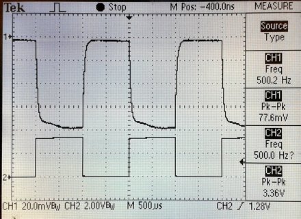
Scope-PD500Hz-out.jpg

...or would it be possible to just schedule the ADC to sample at a steady rate, and then somehow toggle the output based on the ADC sampling? But I think it has to be hardware-triggered to be precisely uniform; eg. same number of clock cycles every time, and a fixed number of cycles between the signal out and the sample points.
 
Last edited:
There is an isr for the continuous adc completion? Maybe you can read the pwm in that and record the adc value if you like that pwm value?

That would be faster that triggering a sample after the fact, and you could bracket it as you see fit recording both numbers
 
(Speaking as a relative noob here, so others may have better advice, but:)

500Hz isn't that fast - you don't really need to use a PWM function for it. If you create your signal in code, you can have your sampling data run in the same block too.

But when you say you want to *sample* the signal, how many samples and at what frequency do you need? That is, do you just need a single sample 300 uS before each output change, or do you want a bunch of samples so you can see the shape of the waveform (a la oscilloscope)?

For reference, I'm routinely driving stepper motors at 62.5kHz with a Teensy LC, and the chunk of code that works out whether to send a pulse or not gets called, well, 62,500 times a second. My output pulses have less jitter than I can see / measure (though that's not saying much with my sight)

Might be worth specifying exactly how much jitter you can cope with - I mean, you say you'd like the same number of clock cycles between samples, but that means (assuming your Teensy is running at 96MHz) a jitter of less than 10nS. Do you *really* need that precision?
 
Thanks for the input. I'm trying to get the best possible accuracy (hopefully better than 16 bits with averaging), and with the signal changing with time, jitter translates into noise. Software methods (ISR) can have quite a bit more than just one cycle of latency, in my experience. It seems plausible that there might be some hardware path to avoid PWM->ADC phase jitter, but I don't know enough about the Freescale architecture to know how to do it.
 
When a sample is done it is fixed at that time spawning the ISR - until the next sample completes. If you wait to request a sample - you wait for it (and averaging samples) to complete.

At that time you read the current PWM output value and since it only changes a 500 times a second and will be [0/1 or delta] and continuous reads are a multiple of 5 to 50 times (with LOW speed sampling - depending on averaging count ) that you can bracket it and record: ADC sample, PWM val, micros(or ticks) and see for yourself how close they group as long as your read and selective recording doesn't take too long and hold up the works. If there is an interrupt collision hitting your timing you can see that in the recorded time value and go to the next sample - assuming it will repeat easily with regularity - but that won't affect the ADC value, just when you got to it.

I'd start with "void adc0_isr(void) {" in "Examples / ADC / analogContinuousRead"
 
Last edited:
For direct PWM (FTM timer) to ADC triggering, you're going to have to dig into the very low-level details of directly manipulating the chip's hardware registers.

You probably want to start with SIM_SOPT7, which is documented in section 12.2.6, starting on page 246.

While you can use interrupts or even DMA, at such a slow speed your simplest approach might be to just check the ADC to see if it's completed a measurement. Even if you want to use interrupts, if you're not already very experienced with them, this simpler way of manual checking would be a good path to follow. You can always leverage success (and gained experience) with simpler ways to build up to more complex ones.
 
Thanks for the good info, PaulS and defragster. Starting with the SIM_SOPT7 tip, I found an App Note that seems to describe what I want to do (take start trigger from FTM through PDB into ADC), with example code: "FlexTimer and ADC Synchronization for Field Oriented Control on Kinetis" http://cache.freescale.com/files/microcontrollers/doc/app_note/AN4410.pdf and also "Tips and Tricks Using PDB in Motor Control Applications on Kinetis" http://cache.freescale.com/files/microcontrollers/doc/app_note/AN4822.pdf

The ANs are for the K40 and K60 families, but hopefully I can translate it to K20, I only need one ADC channel.
 
Last edited:
Status
Not open for further replies.
Back
Top