
You are using an out of date browser. It may not display this or other websites correctly.
You should upgrade or use an alternative browser.
You should upgrade or use an alternative browser.
puzzle, little brain teaser
- Thread starter Frank B
- Start date
- Status
- Not open for further replies.
defragster
Senior Member+
http://www.adampetersen.se/reviews/hackers.htm
My personal favorite is Steve Dompier's invention of the first IO-device for the Altair - playing music on a low-frequency radio by the interference made from writing to different memory locations on the Altair. It's brilliance, it's art, it's programming.
<edit> bet you're not surprised to see me see this quickly <16 mins>. I did the BING search(es) to make sure I got the conceptual wordy things right with the above.
The 960kHz AM radio frequency ( wikipedia.org Medium_wave ) is being produced by the Teensy processor operation and in close proximity it is getting picked up OTA as a fitting signal for the range in question and amplified. Is it done as 'for the Altair' accessing various memory ranges - or perhaps a series of loops or PWM frequencies? Hoping to see the code.
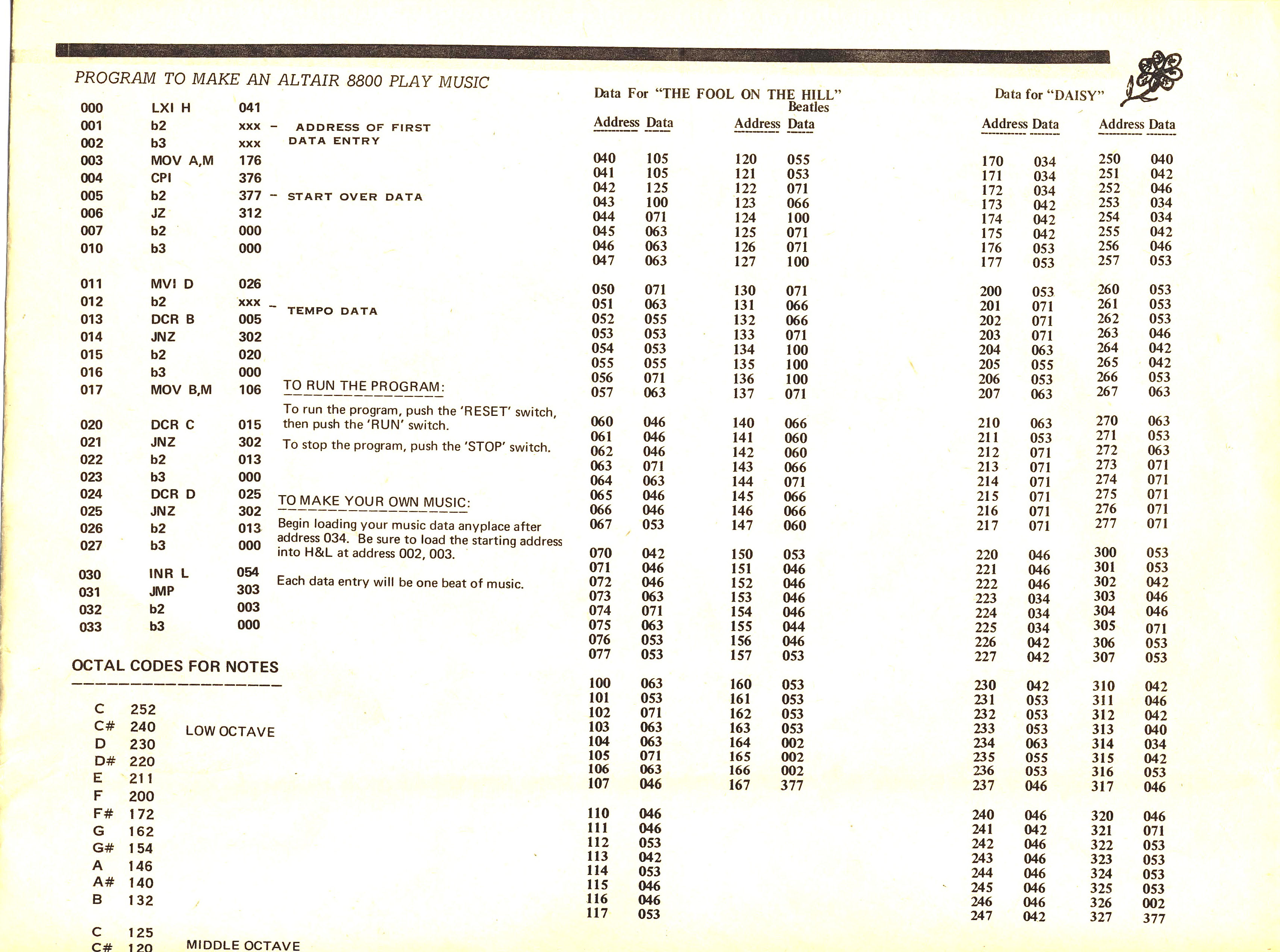
<edit2> Electromagnetic interference :: He left with a computer kit with only 256 bytes of memory. At the April 16, 1975 club meeting Dompier keyed in a small program that played the song "Fool on the Hill" on a nearby AM radio. In the July 1975 Computer Notes, Bill Gates described this as "the best demo program I've seen for the Altair…" Gates could not figure out how the computer could broadcast to the radio.[8] (It was radio frequency interference or static controlled by the timing loops in the program.[9])
https://en.wikipedia.org/wiki/Open_Letter_to_Hobbyists
Sheet Music/BASIC listing of "Fool on the Hill" played on the Altair 8800 computer
My personal favorite is Steve Dompier's invention of the first IO-device for the Altair - playing music on a low-frequency radio by the interference made from writing to different memory locations on the Altair. It's brilliance, it's art, it's programming.
<edit> bet you're not surprised to see me see this quickly <16 mins>. I did the BING search(es) to make sure I got the conceptual wordy things right with the above.
The 960kHz AM radio frequency ( wikipedia.org Medium_wave ) is being produced by the Teensy processor operation and in close proximity it is getting picked up OTA as a fitting signal for the range in question and amplified. Is it done as 'for the Altair' accessing various memory ranges - or perhaps a series of loops or PWM frequencies? Hoping to see the code.
<edit2> Electromagnetic interference :: He left with a computer kit with only 256 bytes of memory. At the April 16, 1975 club meeting Dompier keyed in a small program that played the song "Fool on the Hill" on a nearby AM radio. In the July 1975 Computer Notes, Bill Gates described this as "the best demo program I've seen for the Altair…" Gates could not figure out how the computer could broadcast to the radio.[8] (It was radio frequency interference or static controlled by the timing loops in the program.[9])
https://en.wikipedia.org/wiki/Open_Letter_to_Hobbyists
Sheet Music/BASIC listing of "Fool on the Hill" played on the Altair 8800 computer
Last edited:
pictographer
Well-known member
Those of you interested in keeping secrets inside your Teensy, take note. This is the basis for a classic side-channel attack: record the EMI of the device, perhaps over multiple runs. Correlate to basic operations of the processor. Identify the encryption algorithm from its signature, then extract the key. Search for Differential Power Analysis if you want to read more.
defragster
Senior Member+
Those of you interested in keeping secrets inside your Teensy ... Search for Differential Power Analysis if you want to read more.
Thanks Bing:
http://www.rambus.com/differential-power-analysis/
https://en.wikipedia.org/wiki/Power_analysis
So you have to encrypt your code processing to make random spurious noise - and never encode / decode the same text the same way twice - and not do it in a uniform way - and yet get the same answer - that could add some overhead.
<edit> this wasn't a question - or an attempted alternate answer - it was an ~OT reply in pictographer>
Last edited:
PaulStoffregen
Well-known member
My guess is you've edited the audio lib PWM object, for a divisor of only 50 from the bus clock (48 MHz / 50 = 960 kHz). Teensy can easily produce PWM carriers in the AM radio band. It's pretty amazing the PCB trace with PWM can radiate enough RF for the radio to pick up, since it's on top of a ground plane. Even a short wire extending from the pin would probably help quite a lot.
Of course, the data scaling code must be changed too, so the 16 bit data maps into the limited 0-49 range... perhaps only a small part of the 50 available codes, so the PWM waveform stays closer to 50%. I would imagine if you get too close to either duty cycle extreme, the amount of radiated energy in the carrier becomes quite a bit less.
Maybe you just mapped the signal onto the raw codes with each sample repeated many times. Or maybe you're using another timer to trigger the DMA, since there's no need to rewrite the CV register repeatedly with the same value. Or maybe (and I hope) you might have kept the update at 1 sample per PWM waveform done some really crafty dithering and/or noise-shaped upconversion from 44.1 kHz to 960 kHz? My guess is such conversion might be able to achieve pretty good quality, despite the quantization from 16 to approx 5.6 bits (or less, if not using the entire 0-49 range), especially with sigma-delta noise shaping. From the video, it's hard to tell if the poor quality is due to weak RF, only about 5 bits of sample res, or the radio's speaker, or recording equipment used.
Good luck and have fun")
I had fun, but I can only guess.
Apart from knowing that AM is amplitude modulated carrier and noting no wire or anything else connected on the Teensy (3.2?) but some reduced signal when teensy was not flat over the radio, I realize that you generated a 960 kHz signal that is connected to a trace that runs cross the board, and modulated the radiated energy somehow.
But my guess is that method is very simple
simply put modulated 960 kHz signal (or sub-harmonic) onto DAC as there is no Antialiasing filter on DAC (however I cannot see the connecting trace to DAC).
I will not repeat PWM as Paul mentioned it before.
The display seems to be a bit misleading. It displays 96.0 MHz. But you are right, that is not easy to recognize.
So it is FM and not AM.
As this is the CPU frequency, so you changed the in internal loading capacitors of the Xtal accordingly (modulating the capacitors with fsig/6)
Constantin
Well-known member
I'm glad you think it's simple.
Meanwhile, I'm still stuck at the train station with the train hurtling on in the distance. :-D
Meanwhile, I'm still stuck at the train station with the train hurtling on in the distance. :-D
Link: https://github.com/FrankBoesing/output_fm
I modified the DAC-Output-object - The Teensy modulates its own frequency with dma to the OSC0_CR register.
The quality is, unfortunately, very poor.
I modified the DAC-Output-object - The Teensy modulates its own frequency with dma to the OSC0_CR register.
The quality is, unfortunately, very poor.
- Status
- Not open for further replies.