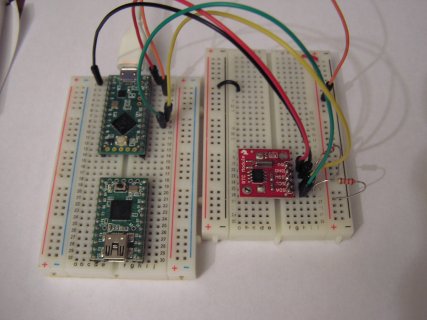
Teensy LC & DS1307: Current Time Weirdness

Status
Not open for further replies.

Jerware

Well-known member
I have a kind of alarm clock built using Teensy LC and a DS1307 for time keeping. I can set alarms using a text file that's read from SD. The times are converted into minutes-into-the-day, and stored in RAM. If the current time (minutes-into-the-day) matches one of the alarms, the user is signaled. I check for a match between alarms and current time once at the top of every minute, whenever "seconds" equals zero.

Sounds good, right? The problem is -- and this has taken awhile to find -- if an alarm is precisely on the top of the hour, every now and then it won't trigger. This is because occasionally the Time library hour() and minute() functions ARE NOT IN SYNC.

I tracked the current time by printing it to the console at the top of every minute for 12 hours. For nine hours, everything was fine, but then hour() jumped back in time one hour for a fraction of a second like this:

8:57:00
8:58:00
8:59:00
8:00:00
9:01:00
9:02:00

I say "fraction of a second" because I assume they're only out of sync for the cycle that I checked minute() and hour() and stored them as variables. I would bet that adding a delay(1) somewhere in the code would be a workaround, but I would like to see this fixed at a lower level on the off chance it is a Time library or Teensy hardware bug. Unfortunately it's a PITA to reproduce. For what it's worth, it also happened an hour later at 10:00, but then not again for 4 hours after which I stopped the execution because....

I'm currently trying the same experiment using a DS3231 instead of a DS1307 and will followup with the results. In the meantime I would appreciate any other perspectives or input on the situation.

On a related note, my "get time" function is run on update and looks like this:

Code:
void getCurrentTime()
{
  currentHour = hour();
  currentMinute = minute();
  currentSecond = second();
}

The Time library is set to sync with the RTC every second, so is it possible that it's occasionally re-syncing in the middle of my function, between currentHour and currentMinute? If so, how would I completely avoid this?
 
Last edited:
Thanks, Paul. Having looked at the Time source now I can see that each call to now() returns fresh time data, so your solution makes sense. (And for what it's worth, the DS3231 exhibited the same problem.)
 
What are the default pins used for connecting a DS1307 to a Teensy LC? I've looked through all the doc. and can't find anything.
I'm guessing 18,19??

TIA
 
Yes, pin 18/A4 is SCL0 and pin 19/A5 is SDA0.

You will probably need 2 pull-up resistors, one between pin 18 and 3.3v and the other between pin 19 and 3.3v, unless your device already has pull-up resistors. Unless your i2c bus is complicated or long, you would want 2.2K or 2.4K resistors.
 
Thanks Michael - Just waiting for the DS chips to arrive, so double-checking before I get into a solder fest...
 
Remember, Teensy LC requires real pullup resistors on the SDA and SCL pins (each connected to 3.3V). With regular Arduino real resistors are optional. With Teensy LC they are required. It will not work if you omit the resistors.
 
Finally got around to trying this but its not working on the LC. I've tested the ds1307 with an Arduino Uno and it works fine. On the LC the Teensy DS1307 lib setTime sketch just returns:
DS1307 Communication Error :-{
Please check your circuitry

Circuitry seems fine 2.2k to 3.3v on LC for SCA/SCL. It seems the SCL and SDA lines are not doing anything(just sit at 3.3v) Howver if I write a simple 'blink' sketch to test them
they flip high/low OK.

Any clues how to get this going?

TIA.
 
datasheet says DS1307 wants to run at 5v. Are you powering DS1307 at 5v? Teensy LC is NOT 5v tolerant. i'm not sure if you can make things work with 3.3v pullups on SCA/SCL ... may need level shifters
 
Yes, pin 18/A4 is SCL0 and pin 19/A5 is SDA0.

You will probably need 2 pull-up resistors, one between pin 18 and 3.3v and the other between pin 19 and 3.3v, unless your device already has pull-up resistors. Unless your i2c bus is complicated or long, you would want 2.2K or 2.4K resistors.

and possibly a lower frequency if it's too long :)
 
You might want to switch to a DS3231. The DS3231 is more accurate, since it includes a temperature sensor to adjust the frequency of the real time clock. Unlike the DS1307, the DS3231 runs at 3.3 to 5v. You can pick them up fairly cheaply from ebay. For example, the cheapest US seller is:

Note, I have used rechargeable coin cell batteries with DS3231 (on Raspberry Pi's), and the battery doesn't last long. It is better to go with a non-rechargeable battery that last for 2-3 years, than trying to keep a rechargeable battery charged.
 
Thanks for the info.

Yes 1307 running at 5v, works fine on Uno. The pullups are fine, LC seems ok. No reason why it should not work as far as I can see.
I would move to DS3231 but already have a load of 1307 bits that I got for Arduino stuff - have used them successfully there many times.

If someone has actually used a 1307 on an LC whats the secret??
 
Other posts (google) show success running 5v DS1307 with 3v3 logic and I2C pins with pulluips to 3v3.
Can you run an i2cscan example and see if scan detects the device?

If you ran the LC with the DS1307 at 5v and had pullups to 5v (the old DS1307 breakout board i have has soldered-in pullups to 5v), then you may have damaged the LC.
 
Last edited:
Thanks for the info.

Yes 1307 running at 5v, works fine on Uno. The pullups are fine, LC seems ok. No reason why it should not work as far as I can see.
I would move to DS3231 but already have a load of 1307 bits that I got for Arduino stuff - have used them successfully there many times.

If someone has actually used a 1307 on an LC whats the secret??

Given the data sheet for the DS1307 (https://datasheets.maximintegrated.com/en/ds/DS1307.pdf) says that the supply voltages MUST be in the range of 4.5v to 5.5v, and given the LC is NOT tolerant of voltages over 3.3v, your only hope is to get a 3.3v -> 5v level shifter that works with i2c. If you are buying the level shifters at retail prices, it is probably cheaper to buy the DS3231.

Other posts (google) show success running 5v DS1307 with 3v3 logic and I2C pins with pulluips to 3v3.
Can you run an i2cscan example and see if scan detects the device?
I would imagine such examples are for the Teensy 3.1 or 3.2 that are tolerant of 5v inputs on digital pins. The Teensy LC is NOT tolerant. I don't remember if I've destroyed an LC with 5v (I have toasted a 3.6 with 5v).
 
Last edited:
How are you powering the 1307 when using the LC? The 1307 is a 5v device.
A simple circuit and code of what you are doing might allow others to see your problem.
 
Good point about 5v -- 3.3v. However if `i'm using 3.3v pullups that is the logic level I'd expect to see.
Running the 1307 at 3.3v supply is a bit out of range but several people have found it works. I did try this but it did nothing.
I'm sure I've used this on 3.3v in the past(with Arduino@ 3.3v) and the logic levels worked ok.

I' tried a scan but the SCL and SCA pins are just sitting at 3.3v. In fact using the wire library to repeatedly write data
with just the pullups connected should show something but it does not.

I've run other types of slave devices that are 5v but with 3.3v logic - as long as the pullups are correct it works
I see the OP (Jerware) has it working with the 1307.

So maybe I'll stop wasting time with this and use a 3231 as suggeste.d (although it uses twice as much board space)
 
I' tried a scan but the SCL and SCA pins are just sitting at 3.3v. In fact using the wire library to repeatedly write data
with just the pullups connected should show something but it does not.
Are you using a scope/analyzer to observe the I2C pins? If you're seeing nothing on SCL, then maybe the LC is damaged?
Are you using a sparkfun DS1307 breakout ? (it has onboard pullups to 5v)
 
Last edited:
Could you paste your code. There may be confusion over pin numbers..has happened in the past. Especially if you can make the pins waggle up and down with a simple blink type sketch but not with wire library.
 
I'm using the circuit as per the datasheet. No backup battery, and I'm not using the Sq out pin. This works Ok if I connect an Arduino to it so the chip appears functional.
The code is the Teensy LC example DS1307 RTC, there are no pin numbers used. According to the LC datasheet it is SDA on 18 and SCL on 19 but, in a post above it is claimed to be the other way round (!). Tried it the other way and no go either LOL.! This is the second LC I've tried and same result - nothing. The scanner example is probing/sending data but it just says 'no I2C' device found.(Although I think DS1307 doesnt respond to this anyway)
I reckon this is a dead-end unless someone can prove it works on an LC.... thanks for all the suggestions anyway.

Set time example:

#include <Wire.h>
#include <TimeLib.h>
#include <DS1307RTC.h>

const char *monthName[12] = {
"Jan", "Feb", "Mar", "Apr", "May", "Jun",
"Jul", "Aug", "Sep", "Oct", "Nov", "Dec"
};

tmElements_t tm;

void setup() {
bool parse=false;
bool config=false;

// get the date and time the compiler was run
if (getDate(__DATE__) && getTime(__TIME__)) {
parse = true;
// and configure the RTC with this info
if (RTC.write(tm)) {
config = true;
}
}

Serial.begin(9600);
while (!Serial) ; // wait for Arduino Serial Monitor
delay(200);
if (parse && config) {
Serial.print("DS1307 configured Time=");
Serial.print(__TIME__);
Serial.print(", Date=");
Serial.println(__DATE__);
} else if (parse) {
Serial.println("DS1307 Communication Error :-{");
Serial.println("Please check your circuitry");
} else {
Serial.print("Could not parse info from the compiler, Time=\"");
Serial.print(__TIME__);
Serial.print("\", Date=\"");
Serial.print(__DATE__);
Serial.println("\"");
}
}

void loop() {
}

bool getTime(const char *str)
{
int Hour, Min, Sec;

if (sscanf(str, "%d:%d:%d", &Hour, &Min, &Sec) != 3) return false;
tm.Hour = Hour;
tm.Minute = Min;
tm.Second = Sec;
return true;
}

bool getDate(const char *str)
{
char Month[12];
int Day, Year;
uint8_t monthIndex;

if (sscanf(str, "%s %d %d", Month, &Day, &Year) != 3) return false;
for (monthIndex = 0; monthIndex < 12; monthIndex++) {
if (strcmp(Month, monthName[monthIndex]) == 0) break;
}
if (monthIndex >= 12) return false;
tm.Day = Day;
tm.Month = monthIndex + 1;
tm.Year = CalendarYrToTm(Year);
return true;
}
 
Last edited:
I've run i2cscan on T3.2 (5v tolerant) using https://www.sparkfun.com/products/12708. ds1307 does respond to scan:

Scanning...
I2C device found at: 0x68
done

And I ran your sketch on T3.2, it works:
DS1307 configured Time=17:05:53, Date=Apr 28 2017

What breakout are you using?
I'm undecided about desoldering the 5v pullups jumper on my breakout to try with LC

I reckon this is a dead-end unless someone can prove it works on an LC
EDIT
OK, i desoldered 5v pullups on breakout and added 2.2K pullups to 3v3. Tested first on T3.2, scan and sketch worked.
Tested on LC, scan and sketch worked: DS1307 configured Time=20:18:25, Date=Apr 28 2017

P4280010.JPG

DS1307 works on LC with 5V power and 2.2k pullups to 3v3.
 
Last edited:
"DS1307 works on LC with 5V power and 2.2k pullups to 3v3. "
Manitou - thanks for testing this. I'm using a DIP IC on a breadboard, SDA A4(18), SCL A5(19). Works fine with Arduino.

last night I updated/reinstalled Arduino/Teensy libs as a precaution. Now it is working!

Thanks again to all for your input
 
Last edited:
Status
Not open for further replies.
Back
Top