Teensy 3.2 Libaries Compatibility?

Status
Not open for further replies.

erek

Active member
Teensy 3.2 - Autonomous Flight Controller

I was looking to make use of the Teensy 3.2 with an Arduino Adapter Shield with the following libraries and was wondering if based on being able to compile a project if that's a good enough indicator to pull the trigger?

#include <Servo.h>
#include <PID_v1.h>
#include <Adafruit_GPS.h> /* Modified in Adafruit_GPS.cpp : "isDigit()" -> "isdigit()" and "isAlpha()" -> "isalpha()" cases to work with Teensy compiling. Erik */
#include <Wire.h>
#include <Adafruit_Sensor.h>
#include <Adafruit_BNO055.h>
#include <utility/imumaths.h>
#include <stdlib.h>

http://pastebin.com/Gd2jNQB6


"Opening Teensy Loader...

Sketch uses 41,696 bytes (15%) of program storage space. Maximum is 262,144 bytes.
Global variables use 5,480 bytes (8%) of dynamic memory, leaving 60,056 bytes for local variables. Maximum is 65,536 bytes."


The response I got over at adafruit forums :

"Re: Teensy 3.2 Libaries Compatibility?

by adafruit_support_bill on Thu Oct 15, 2015 10:55 am
I don't see any that would have obvious problems such as pin-conflicts on the Teensy. You might check over at pjrc.com (the designers of the Teensy) for a second opinion."
 
Last edited:
This looks like it should work. There's a 1 second delay in setup, which is good.

I haven't personally tested all those libraries, but there haven't been any reports of troubles with those ones either.
 
awesome, i have purchased a Teensy 3.2.

Going to be using an Adafruit BNO055 Breakout Board (I2C connection), Adafruit Ultimate GPS+Data Logger Shield, Adafruit Motor Shield (Digital PWM Pin 9), and Adafruit PowerBoost 500 Shield (3.7V 2200mAh Lithium Ion for now). Seems the Uno wouldn't have enough memory resources to handle my project that will take in current orientation (BNO055) and position (GPS, possibly need Kalman Filtering on this data) as inputs into PID Control Loops (Arduino PIDLibrary) and expected orientation and position values as the other input to output corrections to a Servo Motor drive mechanism to steer a Parafoil-like craft to a preset target destination.

I am excited for this challenge
 
Last edited:
I haven't looked at the parts, but one thing to check when using Arduino parts on a Teensy, is whether the boards need 5v or 3.3v. If they need 5v, you may need to do level shifting. If they are 3.3v, check what their power draw is (the Teensy 3.2 has a lot more headroom on the 3.3v power rail than older Teensy's, so I imagine you should be ok).
 
I haven't looked at the parts, but one thing to check when using Arduino parts on a Teensy, is whether the boards need 5v or 3.3v. If they need 5v, you may need to do level shifting. If they are 3.3v, check what their power draw is (the Teensy 3.2 has a lot more headroom on the 3.3v power rail than older Teensy's, so I imagine you should be ok).

The BNO055 Adafruit Breakout needs 5V ( https://learn.adafruit.com/adafruit-bno055-absolute-orientation-sensor/wiring-and-test )


The Adafruit Ultimate GPS + Data Logger Shield needs 5V ( basing this on the non-shield version : https://learn.adafruit.com/adafruit-ultimate-gps/arduino-wiring )

- How would I go about level shifting ?


From this thread hear about the Adafruit Ultimate GPS Breakout there is no mentioning of doing level shifting : https://forum.pjrc.com/threads/95-GPS-working!


i was planning on using this SparkFun Teensy Arduino Adapter : https://www.sparkfun.com/products/13288
 
Seems the SparkFun Arduino Adapter has a voltage regulator, think this will suffice?

L7805 voltage regulator, a three-terminal positive regulator with a 5V fixed output voltage. This fixed regulator provides a local regulation, internal current limiting, thermal shut-down control, and safe area protection for your project. Each one of these voltage regulators can output a max current of 1.5A.

Features:

Output Voltage: 5V
Output Current: 1.5A
Thermal Overload Protection
Short Circuit Protection
Output Transition SOA Protection
 
The BNO055 can take input from 3.3v, so you don't need to do level shifting. Since it is i2c, you will NEED to add 2 4.7K pull-up resistors (2 resistors, 1 each wired between A4/A5 and 3.3v). Similarly, the Ultimate GPS can be powered by 3.3v, so you probably don't need level shifters.
 
The BNO055 can take input from 3.3v, so you don't need to do level shifting. Since it is i2c, you will NEED to add 2 4.7K pull-up resistors (2 resistors, 1 each wired between A4/A5 and 3.3v). Similarly, the Ultimate GPS can be powered by 3.3v, so you probably don't need level shifters.

Thank you!

Shouldn't be too bad of a deal to add those resistors for each of the A4/A5 since i'll be using a breadboard,

also been working on powering the primary Teensy/Arduino Shield itself ...


So with a "3.7V LiPo" -> "3.3V Buck Converter" -> "3.3V JST" (Arduino Adapter Shield) power setup, I think i'll be able to make use of additional Shields that require 5V off the header stack due to the 5V Voltage regulator on the adapter shield itself
 
I think i'll be able to make use of additional Shields that require 5V off the header stack due to the 5V Voltage regulator on the adapter shield itself

Looking at the hookup guide it appears that you'll need to supply 4-12 volts externally to get 5v from that shield. You won't get there from LiPo power alone. EDIT: I was referring to this product - https://www.sparkfun.com/products/13288; I missed the power shield (which will give you your 5v).

Just FWIW.

Regards,

Brad.
 
Last edited:
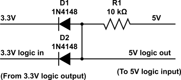
attempting to simulate 3.3V level shifter to 5V with this schematic, i don't seem to understand how to hook up the power?

vk0vs.png

Here's my attempt with a 9V battery source :

https://123d.circuits.io/circuits/1124543-the-unnamed-circuit/edit#schematic
 
The BNO055 can take input from 3.3v, so you don't need to do level shifting. Since it is i2c, you will NEED to add 2 4.7K pull-up resistors (2 resistors, 1 each wired between A4/A5 and 3.3v). Similarly, the Ultimate GPS can be powered by 3.3v, so you probably don't need level shifters.

is that 3x 4.7L resistors then? I purchased two packs, 1/4 watt and 1/8 watt 4.7K ohm resistors

1x on A4
1x on A5

and

1x on the 3.3V positive line?
 
Last edited:
You need two resistors (resistors have to connect two pins). One goes from A4 to the 3.3v positive line. The other goes from A5 to the 3.3v positive line. Pull-up resistors go from the data pin to the appropriate power pin (3.3v in this case), while pull-down resistors go from the data pin to ground.
 
Having an issue getting the GPS unit to work, it's the Adafruit Ultimate GPS+Data Logger Shield.

context:

Teensy 3.2 with Arduino Adapter Shield

Adafruit Ultimate GPS+Data Logger Shield On Top

Adafruit Bosh BNO055 9 DOF Breakout Board (A4/A5) 3.3V and GND


-----

This statement returns the firmware version just fine though : Serial.println(PMTK_Q_RELEASE);

The Bosch unit is working through the stack on top of the GPS shield just fine.


Code:
// Test code for Adafruit GPS modules using MTK3329/MTK3339 driver
//
// This code shows how to listen to the GPS module in an interrupt
// which allows the program to have more 'freedom' - just parse
// when a new NMEA sentence is available! Then access data when
// desired.
//
// Tested and works great with the Adafruit Ultimate GPS module
// using MTK33x9 chipset
//    ------> http://www.adafruit.com/products/746
// Pick one up today at the Adafruit electronics shop 
// and help support open source hardware & software! -ada

#include <Adafruit_GPS.h>
#include <SoftwareSerial.h>


// If you're using a GPS module:
// Connect the GPS Power pin to 5V
// Connect the GPS Ground pin to ground
// If using software serial (sketch example default):
//   Connect the GPS TX (transmit) pin to Digital 3
//   Connect the GPS RX (receive) pin to Digital 2
// If using hardware serial (e.g. Arduino Mega):
//   Connect the GPS TX (transmit) pin to Arduino RX1, RX2 or RX3
//   Connect the GPS RX (receive) pin to matching TX1, TX2 or TX3

// If you're using the Adafruit GPS shield, change 
// SoftwareSerial mySerial(3, 2); -> SoftwareSerial mySerial(8, 7);
// and make sure the switch is set to SoftSerial

// If using software serial, keep these lines enabled
// (you can change the pin numbers to match your wiring):
SoftwareSerial mySerial(3, 2);

//Adafruit_GPS GPS(&mySerial);
// If using hardware serial (e.g. Arduino Mega), comment
// out the above six lines and enable this line instead:
Adafruit_GPS GPS(&Serial1);


// Set GPSECHO to 'false' to turn off echoing the GPS data to the Serial console
// Set to 'true' if you want to debug and listen to the raw GPS sentences. 
#define GPSECHO  true

// this keeps track of whether we're using the interrupt
// off by default!
boolean usingInterrupt = false;
void useInterrupt(boolean); // Func prototype keeps Arduino 0023 happy

void setup()  
{

  // connect at 115200 so we can read the GPS fast enough and echo without dropping chars
  // also spit it out
  Serial.begin(115200);
  //Serial.println("Adafruit GPS library basic test!");

  // 9600 NMEA is the default baud rate for Adafruit MTK GPS's- some use 4800
  GPS.begin(9600);

  // uncomment this line to turn on RMC (recommended minimum) and GGA (fix data) including altitude
  GPS.sendCommand(PMTK_SET_NMEA_OUTPUT_RMCGGA);
  // uncomment this line to turn on only the "minimum recommended" data
  //GPS.sendCommand(PMTK_SET_NMEA_OUTPUT_RMCONLY);
  // For parsing data, we don't suggest using anything but either RMC only or RMC+GGA since
  // the parser doesn't care about other sentences at this time

  // Set the update rate
  GPS.sendCommand(PMTK_SET_NMEA_UPDATE_1HZ);   // 1 Hz update rate
  // For the parsing code to work nicely and have time to sort thru the data, and
  // print it out we don't suggest using anything higher than 1 Hz

  // Request updates on antenna status, comment out to keep quiet
  GPS.sendCommand(PGCMD_ANTENNA);

  // the nice thing about this code is you can have a timer0 interrupt go off
  // every 1 millisecond, and read data from the GPS for you. that makes the
  // loop code a heck of a lot easier!
  //useInterrupt(true);

  delay(1000);
  // Ask for firmware version
  Serial.println(PMTK_Q_RELEASE);
}


uint32_t timer = millis();
void loop()                     // run over and over again
{


  // in case you are not using the interrupt above, you'll
  // need to 'hand query' the GPS, not suggested :(
  if (! usingInterrupt) {
    // read data from the GPS in the 'main loop'
    char c = GPS.read();
    // if you want to debug, this is a good time to do it!
    if (GPSECHO)
      if (c) Serial.print(c);
  }

  // if a sentence is received, we can check the checksum, parse it...
  if (GPS.newNMEAreceived()) {
    // a tricky thing here is if we print the NMEA sentence, or data
    // we end up not listening and catching other sentences! 
    // so be very wary if using OUTPUT_ALLDATA and trytng to print out data
    //Serial.println(GPS.lastNMEA());   // this also sets the newNMEAreceived() flag to false

    if (!GPS.parse(GPS.lastNMEA()))   // this also sets the newNMEAreceived() flag to false
      return;  // we can fail to parse a sentence in which case we should just wait for another
  }

  // if millis() or timer wraps around, we'll just reset it
  if (timer > millis())  timer = millis();

  // approximately every 2 seconds or so, print out the current stats
  if (millis() - timer > 1000) { 
    timer = millis(); // reset the timer


    Serial.print("\nTime: ");
    Serial.print(GPS.hour, DEC); 
    Serial.print(':');
    Serial.print(GPS.minute, DEC); 
    Serial.print(':');
    Serial.print(GPS.seconds, DEC); 
    Serial.print('.');
    Serial.println(GPS.milliseconds);
    Serial.print("Date: ");
    Serial.print(GPS.day, DEC); 
    Serial.print('/');
    Serial.print(GPS.month, DEC); 
    Serial.print("/20");
    Serial.println(GPS.year, DEC);
    Serial.print("Fix: "); 
    Serial.print((int)GPS.fix);
    Serial.print(" quality: "); 
    Serial.println((int)GPS.fixquality); 
    if (GPS.fix) {
      Serial.print("Location: ");
      Serial.print(GPS.latitude, 4); 
      Serial.print(GPS.lat);
      Serial.print(", "); 
      Serial.print(GPS.longitude, 4); 
      Serial.println(GPS.lon);

      Serial.print("Speed (MPH): "); 
      Serial.println(GPS.speed);
      Serial.print("Angle: "); 
      Serial.println(GPS.angle);
      Serial.print("Altitude (Ft): "); 
      Serial.println(GPS.altitude);
      Serial.print("Satellites: "); 
      Serial.println((int)GPS.satellites);

    }  
  }
}
 
Having an issue getting the GPS unit to work, it's the Adafruit Ultimate GPS+Data Logger Shield.

Maybe post a photo of how you've actually connected it to Teensy.

A common error involves connecting RX to RX1 and TX to TX1, rather than connecting the GPS transmit to Teensy's receive, and vise-versa.
 
i did notice this on the adafruit learn page about the SoftwareSerial and the Leonardo :

Direct Connection with Jumpers on Leonardo

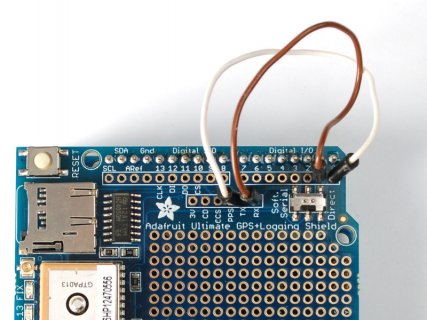
If you have a Leonardo we have to do a funky trick where we swap the Direct connect wires (because the processor chip acts like the USB/Serial converter rather than having a seperate chip. The upshot is you'll need two wires. For basic testing as long as the wires touch the two sets of pads, you'll be able to continue with this very basic test. We don't suggest soldering them yet in since as long as the GPS works, you can go forward and use software serial if you prefer

Select Software Serial on the switch. Connect a wire from the TX pad to digital 0 and a wire from the RX pad to digital 1.
adafruit_products_leodirect.jpg

https://learn.adafruit.com/adafruit-ultimate-gps-logger-shield/direct-connect
 
The code you posted in #13 is using Serial1, which is pins 0 and 1. Obviously this code can't work with the signals connected to different pins.

You'll need to use those 2 wires to connect the pins to 0 and 1, the same as the photo for Leonardo.
 
The code you posted in #13 is using Serial1, which is pins 0 and 1. Obviously this code can't work with the signals connected to different pins.

You'll need to use those 2 wires to connect the pins to 0 and 1, the same as the photo for Leonardo.

Will attempt your suggestion,

here's what i noticed when trying mySerial (SoftwareSerial mySerial(8,7))


Code:
// Test code for Adafruit GPS modules using MTK3329/MTK3339 driver
//
// This code shows how to listen to the GPS module in an interrupt
// which allows the program to have more 'freedom' - just parse
// when a new NMEA sentence is available! Then access data when
// desired.
//
// Tested and works great with the Adafruit Ultimate GPS module
// using MTK33x9 chipset
//    ------> http://www.adafruit.com/products/746
// Pick one up today at the Adafruit electronics shop 
// and help support open source hardware & software! -ada

#include <Adafruit_GPS.h>
#include <SoftwareSerial.h>


// If you're using a GPS module:
// Connect the GPS Power pin to 5V
// Connect the GPS Ground pin to ground
// If using software serial (sketch example default):
//   Connect the GPS TX (transmit) pin to Digital 3
//   Connect the GPS RX (receive) pin to Digital 2
// If using hardware serial (e.g. Arduino Mega):
//   Connect the GPS TX (transmit) pin to Arduino RX1, RX2 or RX3
//   Connect the GPS RX (receive) pin to matching TX1, TX2 or TX3

// If you're using the Adafruit GPS shield, change 
// SoftwareSerial mySerial(3, 2); -> SoftwareSerial mySerial(8, 7);
// and make sure the switch is set to SoftSerial

// If using software serial, keep these lines enabled
// (you can change the pin numbers to match your wiring):
SoftwareSerial mySerial(8,7);

//Adafruit_GPS GPS(&mySerial);
// If using hardware serial (e.g. Arduino Mega), comment
// out the above six lines and enable this line instead:
Adafruit_GPS GPS(&mySerial);


// Set GPSECHO to 'false' to turn off echoing the GPS data to the Serial console
// Set to 'true' if you want to debug and listen to the raw GPS sentences. 
#define GPSECHO  true

// this keeps track of whether we're using the interrupt
// off by default!
boolean usingInterrupt = false;
void useInterrupt(boolean); // Func prototype keeps Arduino 0023 happy

void setup()  
{

  // connect at 115200 so we can read the GPS fast enough and echo without dropping chars
  // also spit it out
  Serial.begin(115200);
  //Serial.println("Adafruit GPS library basic test!");

  // 9600 NMEA is the default baud rate for Adafruit MTK GPS's- some use 4800
  GPS.begin(9600);

  // uncomment this line to turn on RMC (recommended minimum) and GGA (fix data) including altitude
  GPS.sendCommand(PMTK_SET_NMEA_OUTPUT_RMCGGA);
  // uncomment this line to turn on only the "minimum recommended" data
  //GPS.sendCommand(PMTK_SET_NMEA_OUTPUT_RMCONLY);
  // For parsing data, we don't suggest using anything but either RMC only or RMC+GGA since
  // the parser doesn't care about other sentences at this time

  // Set the update rate
  GPS.sendCommand(PMTK_SET_NMEA_UPDATE_1HZ);   // 1 Hz update rate
  // For the parsing code to work nicely and have time to sort thru the data, and
  // print it out we don't suggest using anything higher than 1 Hz

  // Request updates on antenna status, comment out to keep quiet
  GPS.sendCommand(PGCMD_ANTENNA);

  // the nice thing about this code is you can have a timer0 interrupt go off
  // every 1 millisecond, and read data from the GPS for you. that makes the
  // loop code a heck of a lot easier!
  //useInterrupt(true);

  delay(1000);
  // Ask for firmware version
  Serial.println(PMTK_Q_RELEASE);
}


uint32_t timer = millis();
void loop()                     // run over and over again
{


  // in case you are not using the interrupt above, you'll
  // need to 'hand query' the GPS, not suggested :(
  if (! usingInterrupt) {
    // read data from the GPS in the 'main loop'
    char c = GPS.read();
    // if you want to debug, this is a good time to do it!
    if (GPSECHO)
      if (c) Serial.print(c);
  }

  // if a sentence is received, we can check the checksum, parse it...
  if (GPS.newNMEAreceived()) {
    // a tricky thing here is if we print the NMEA sentence, or data
    // we end up not listening and catching other sentences! 
    // so be very wary if using OUTPUT_ALLDATA and trytng to print out data
    //Serial.println(GPS.lastNMEA());   // this also sets the newNMEAreceived() flag to false

    if (!GPS.parse(GPS.lastNMEA()))   // this also sets the newNMEAreceived() flag to false
      return;  // we can fail to parse a sentence in which case we should just wait for another
  }

  // if millis() or timer wraps around, we'll just reset it
  if (timer > millis())  timer = millis();

  // approximately every 2 seconds or so, print out the current stats
  if (millis() - timer > 1000) { 
    timer = millis(); // reset the timer


    Serial.print("\nTime: ");
    Serial.print(GPS.hour, DEC); 
    Serial.print(':');
    Serial.print(GPS.minute, DEC); 
    Serial.print(':');
    Serial.print(GPS.seconds, DEC); 
    Serial.print('.');
    Serial.println(GPS.milliseconds);
    Serial.print("Date: ");
    Serial.print(GPS.day, DEC); 
    Serial.print('/');
    Serial.print(GPS.month, DEC); 
    Serial.print("/20");
    Serial.println(GPS.year, DEC);
    Serial.print("Fix: "); 
    Serial.print((int)GPS.fix);
    Serial.print(" quality: "); 
    Serial.println((int)GPS.fixquality); 
    if (GPS.fix) {
      Serial.print("Location: ");
      Serial.print(GPS.latitude, 4); 
      Serial.print(GPS.lat);
      Serial.print(", "); 
      Serial.print(GPS.longitude, 4); 
      Serial.println(GPS.lon);

      Serial.print("Speed (MPH): "); 
      Serial.println(GPS.speed);
      Serial.print("Angle: "); 
      Serial.println(GPS.angle);
      Serial.print("Altitude (Ft): "); 
      Serial.println(GPS.altitude);
      Serial.print("Satellites: "); 
      Serial.println((int)GPS.satellites);

    }  
  }
}


sketch_oct20a:39: error: no matching function for call to 'Adafruit_GPS::Adafruit_GPS(SoftwareSerial*)'
sketch_oct20a.ino:39:27: note: candidates are:
In file included from sketch_oct20a.ino:14:0:
C:\Program Files (x86)\Arduino\libraries\Adafruit-GPS-Library-master/Adafruit_GPS.h:111:3: note: Adafruit_GPS::Adafruit_GPS(HardwareSerial*)
Adafruit_GPS(HardwareSerial *ser); // Constructor when using HardwareSerial
^
C:\Program Files (x86)\Arduino\libraries\Adafruit-GPS-Library-master/Adafruit_GPS.h:111:3: note: no known conversion for argument 1 from 'SoftwareSerial*' to 'HardwareSerial*'
C:\Program Files (x86)\Arduino\libraries\Adafruit-GPS-Library-master/Adafruit_GPS.h:100:7: note: constexpr Adafruit_GPS::Adafruit_GPS(const Adafruit_GPS&)
class Adafruit_GPS {
^
C:\Program Files (x86)\Arduino\libraries\Adafruit-GPS-Library-master/Adafruit_GPS.h:100:7: note: no known conversion for argument 1 from 'SoftwareSerial*' to 'const Adafruit_GPS&'
C:\Program Files (x86)\Arduino\libraries\Adafruit-GPS-Library-master/Adafruit_GPS.h:100:7: note: constexpr Adafruit_GPS::Adafruit_GPS(Adafruit_GPS&&)
C:\Program Files (x86)\Arduino\libraries\Adafruit-GPS-Library-master/Adafruit_GPS.h:100:7: note: no known conversion for argument 1 from 'SoftwareSerial*' to 'Adafruit_GPS&&'
no matching function for call to 'Adafruit_GPS::Adafruit_GPS(SoftwareSerial*)'


this error seems to be around this :

Code:
#ifdef __AVR__
  #if ARDUINO >= 100 
    Adafruit_GPS(AltSoftSerial *ser); // Constructor when using AltSoftSerial
  #else
    Adafruit_GPS(NewSoftSerial  *ser); // Constructor when using NewSoftSerial
  #endif
#endif
  Adafruit_GPS(HardwareSerial *ser); // Constructor when using HardwareSerial
 
Last edited:
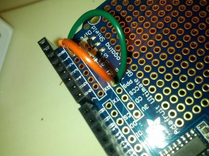
after jumping RX to Digital Pin 1, and TX to Digital Pin 0 i'm still not up and running. Went with a pure Hardware Serial setup also

(no shorts)

IMG_20151021_023056.jpg
 
Change the slide switch to "Direct" - not "Soft-Serial". The two jumper wires are not needed. Use the code from reply #13.
 
Change the slide switch to "Direct" - not "Soft-Serial". The two jumper wires are not needed. Use the code from reply #13.

Same Results :

"Time: 0:0:0.0
Date: 0/0/200
Fix: 0 quality: 0"


switch set to Direct, no pins jumpered, and using code from post #13
 
Perhaps try running File > Examples > Teensy > USB_Serial > USBtoSerial.

That sketch will just relay data between Serial1 and Serial, which you can access in the Arduino Serial Monitor. If that Adafruit GPS module is sending anything, you should see it.

At least confirming the GPS is sending data might be good, before pouring a lot more work into getting any of these parsing libraries working.
 
no luck with the USBtoSerial, but I tested the GPS with an Arduino Uno and SoftwareSerial Pins 8,7 and it's working


Code:
/* USB to Serial - Teensy becomes a USB to Serial converter
   [url]http://dorkbotpdx.org/blog/paul/teensy_as_benito_at_57600_baud[/url]

   You must select Serial from the "Tools > USB Type" menu

   This example code is in the public domain.
*/

// set this to the hardware serial port you wish to use
#define HWSERIAL Serial1

unsigned long baud = 9600;
const int reset_pin = 4;
const int led_pin = 13;  // 13 = Teensy 3.X & LC
                         // 11 = Teensy 2.0
                         //  6 = Teensy++ 2.0
void setup()
{

  delay(3000);
  pinMode(led_pin, OUTPUT);
  digitalWrite(led_pin, LOW);
  digitalWrite(reset_pin, HIGH);
  pinMode(reset_pin, OUTPUT);
  Serial.begin(baud);	// USB, communication to PC or Mac
  HWSERIAL.begin(baud);	// communication to hardware serial
Serial.println("test");

}

long led_on_time=0;
byte buffer[80];
unsigned char prev_dtr = 0;

void loop()
{
  unsigned char dtr;
  int rd, wr, n;

  // check if any data has arrived on the USB virtual serial port
  rd = Serial.available();
  if (rd > 0) {
    // check if the hardware serial port is ready to transmit
    wr = HWSERIAL.availableForWrite();
    if (wr > 0) {
      // compute how much data to move, the smallest
      // of rd, wr and the buffer size
      if (rd > wr) rd = wr;
      if (rd > 80) rd = 80;
      // read data from the USB port
      n = Serial.readBytes((char *)buffer, rd);
      // write it to the hardware serial port
      HWSERIAL.write(buffer, n);
      // turn on the LED to indicate activity
      digitalWrite(led_pin, HIGH);
      led_on_time = millis();
    }
  }

  // check if any data has arrived on the hardware serial port
  rd = HWSERIAL.available();
  if (rd > 0) {
    // check if the USB virtual serial port is ready to transmit
    wr = Serial.availableForWrite();
    if (wr > 0) {
      // compute how much data to move, the smallest
      // of rd, wr and the buffer size
      if (rd > wr) rd = wr;
      if (rd > 80) rd = 80;
      // read data from the hardware serial port
      n = HWSERIAL.readBytes((char *)buffer, rd);
      // write it to the USB port
      Serial.write(buffer, n);
      // turn on the LED to indicate activity
      digitalWrite(led_pin, HIGH);
      led_on_time = millis();
    }
  }

  // check if the USB virtual serial port has raised DTR
  dtr = Serial.dtr();
  if (dtr && !prev_dtr) {
    digitalWrite(reset_pin, LOW);
    delayMicroseconds(250);
    digitalWrite(reset_pin, HIGH);
  }
  prev_dtr = dtr;

  // if the LED has been left on without more activity, turn it off
  if (millis() - led_on_time > 3) {
    digitalWrite(led_pin, LOW);
  }

  // check if the USB virtual serial wants a new baud rate
  if (Serial.baud() != baud) {
    baud = Serial.baud();
    if (baud == 57600) {
      // This ugly hack is necessary for talking
      // to the arduino bootloader, which actually
      // communicates at 58824 baud (+2.1% error).
      // Teensyduino will configure the UART for
      // the closest baud rate, which is 57143
      // baud (-0.8% error).  Serial communication
      // can tolerate about 2.5% error, so the
      // combined error is too large.  Simply
      // setting the baud rate to the same as
      // arduino's actual baud rate works.
      HWSERIAL.begin(58824);
    } else {
      HWSERIAL.begin(baud);
    }
  }
}
 
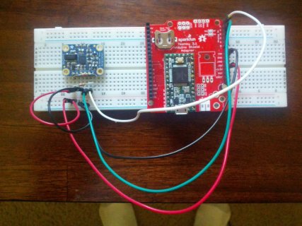
Having another issue also just noticed that the Bosch BNO055 9 DOF BreakOut Board only works if i'm plugging into the header stacks of the GPS shield when that is plugged into the arduino shield adapter. can't get the BNO055 working directly to the arduin shield A4/A5 GND 3.3V. it's quite strange, but if i plug into the same exact positions on the GPS header stacks it works. really starting to burn out here on all of this


IMG_20151021_102934.jpg
 
Status
Not open for further replies.
Back
Top