Bus + External AVR chips vs. local port expanders + longwires

Status
Not open for further replies.

Dande

Member
Hi,
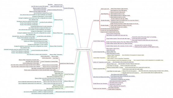
I need some help deciding on which way to go. I am currently automating some stuff on my aquariums like measuring water values, water flows, controlling the heating, pumps, light, semi-automatic water exchenge, carbon dioxide injection, some weight measurements and stuff like that. There should also be some logging of measurements. Main controller will be a Teensy 3.2. Currently I am working on getting the individual functions to work on the mechanics/eletronics side. Programming will be one of the next steps. There will be some space in between the individual parts of the system. I expect 2m to 6m distance from the main controller to the individual parts of the system. The signals are mainly digital signals switching a valve or something similar. Some are PWM signals (LEDs for lighting and pump control). A few are analog for measurements. Most functions are not very time critical (accuracy of 1s is definitely ok) but some like dosing fertilizer needs to be more accurate (~0.1s accuracy).

My problem is the question how to interface the remote functions. There are two main ideas:
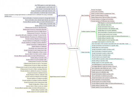
  1. Bus system: I could use some sort of bus system (CAN bus or RS485 or?) and remote logic (either some cheap AVR chip or another Teensy 3.2 or a Teensy LC). The advantage would be that most functions would be implemented in the remote logic and these functions are limited (easier to maintain and verify). Time critical functions could be controlled easily and high frequency signals only have to reach a short way. The system would also be better scalable (maybe even up to controlling 2 aquariums from one main controller). The communciation would be very limited as the main controller only would need to initiate a function not to monitor it closely. Therefore something like 125kbaud would be ok for sure. But it is a lot of effort to have "intelligence" in every part and it might be expansive. Additonally I never did something like this before (but I guess I could manage that).
  2. Port expanders: The Teensy coould control everything directly. In order to have enough I/O pins I would need some port expanders. As I can't stop everything else for time critical functions the tradeoff between different functions might be difficult and risky. There are also very many function interfering with each other which I fear will give me some nightmares. The PWM signals will also have some high frequency component. For the LED lighting I wan't to use no less then 1kHz of PWM frequency (i like to take photos of my fish and slow PWM is a nightmare for that) with no less then 12bits of PWM resolution (=4096 levels of intensity) and the signal needs to be quiet clean in order to work properly.
I started with the idea to implement the second version but now I am wondering if this is the best solution. I somehow get the feeling that the first version can be handled easier. What do you think? Or mixing both ideas by having additional "intelligence" for complex and time critcal functions and interfacing the "easy stuff" from the main controller. Any suggestions for a bus that is easy to implement and not to expansive? Any sort of comment is appreciated.

Thanks
Daniel
 
Long wires can be tricky. Certainly for data, RS485 is excellent over long distance.

Running fairly low speed PWM and analog signals over long wires can sometimes work. The key is to keep each wire and its return ground close together, ideally as a twisted pair.

Several problems come into play with long wires. If you run both power+ground and signals over a long distance, ground shift can become an issue. The resistance of the wires and connectors adds up to a voltage drop when current flows. So if you send a logic low, which is zero volts at the transmitter, it can appear to become a negative voltage at the receiver if the ground has shifted upward due to current flow. Most RS485 chips are designed to proper receive signals that have shifted as much as 5 volts up or down. Most ordinary chips can only handle about -0.3 volts before you start conducting current through their ESD protection diodes.

Of course, other problems like signal reflections and interference can be issues too, but those can be addressed by adding resistors and shielding.
 
I would first make a list of everything you need to control and the ways you can control those items. And the requirements for each thing you need to drive. Know your project requirements will help with determining the best ways to go about making it.
 
I did some thinking on the requirements this evening but to be honest I am not sure how to implement all of this. I am neither very experienced in electronics nor in software development. I am a physicist that has some experience in electronics (due to the fact that I had to build some circuits) and some experience in programming (mainly evaluation algorithms in Matlab, but also some controlling with Labview and some small projects in C/C++). Basically I am experiences enough to see points which can/will cause trouble but solving this is an other issue. I will continue my thoughts tomorrow and most probably will come back with some additional questions.

Thank you so far
Daniel
 
A somewhat offtopic advice: Before lighting your aquarium(s) with PWM'ed LEDs please make shure the PWM frequency is high enough for the animals to be indistinguishable from normal, continuous lighting. Some aquatic lifeforms are able to see flickering at much higher frequencies than us humans are. 1kHz seems plenty for our needs, but may be too slow.

Ben
 
Ok guys, here is a list what I need to control. I made groups with the kind of signal that I need to control them. Sorry but it is a long list but the project has lots of different aspects.

Digital Signals:
  • PWM Signals:
    I need to control light intensity by providing PWM signals to some LEDs. Most probably I will be using 4 different channels (warm white, cold white, red, moon light). Frequency will be ~1kHz. The cable from the main controller to the LED drivers will be ~2m-3m. Additonally the PWM signal needs to be upated roughly once per second to get nice and smooth intensity changes.
    The speed of some pumps needs to be adjusted using PWM signals. The number of the signals will depend on how far I want to go with automation. Nearly all of the pumps are located next to each other, cable length to main controller appr. 2m. One for the water exchange will need a longer cable (~10m). Frequency of the signal is not that critical. A few 100Hz are ok for sure. Resolution of the signal is not that important. For the pumps used to inject fertilizer the timing needs to be accurate (duration the pump is operated needs to be controlled to less then 0.2s jitter, 0.1s would be preferred).
  • Digital Control Signals:
    Controlling Valves using a logic signal (0V off, 5V on) as well as switching some function on or off via relais (Filter, Heating, ...) should be an easy task. The signals need to be stable but they are not changed often. Most of them maybe 2 or 3 times a day some might change a few times per hour. Distances for these signals are no more then 5 meters.
  • Digital Input Signals:
    The flow meters provide a digital signal. A pulse equals a certain amount of water passing through the flow meter. They use a 3 wire connection for this (GND, VDD and Signal). Power consumption is low (I measured 3mA when operated from a 3V3 source). The signal is quiet nice (step flanks) even when using a few meters. The signal frequency can reach from 1Hz to 300Hz. It is necessary to count the pulses either to measure a water volume (for water exchange) or a flow through a tube (checking that the flow is as expected by counting the pulses per second). Currently I use interrupts the call a function that adds one to a variable. But this might not be the best solution.

Analog Signals:
  • Temperature measurements using thermistors:
    The thermistors I use have either 10kOhm or 50kOhm resistance. I use them in a voltage divider with a precision resistor and measure the voltage using a ADC. I can measure the thermistor characteristics at work by comparing them with a precision thermometer (0.1K accuracy traceable to national standards). Due to the high resistance of the thermistors long wires are no problem and temperatures can't change quickly (so I can use lots of averaging either on the analog signal side or in software).
  • Glass electrodes for pH, redox measurement:
    Tricky measurement as these electrodes generate a voltage which is proportional to the value of interest but their impedance is huge (typically 1GOhm to 100GOhm). The electrodes come with pre installed wires (and connectors) which are long enough to reach the main controller. Tricky part is to amplify the signal (fA input bias OpAmps) and to get rid of all the noise which couples into the signal by shielding and averaging. I need to do some more testing (and find the time for that) but I think I can solve that. After that stage of frst amplification everything else isn't complicated.
    For those who wonder what these measurements are used for: pH measurement is used to dose the CO2 injected into the water. Redox value is a good indicator if something goes wrong in the aquarium. Normally you can see this by looking at the fish but if you are away for some days such a value is a good indicator that can be checked remotely.
  • Water conductivity measurement:
    Not really started yet. The conductivity of the water is typically measured using two electrodes wired in series with a known resistor (voltage divider). If the characteristics of the electrodes is known you can calculate the water conductivity from the measured voltage. Issue here is that polarity of the signal needs to be altered to avoid electrolysis (typical frequencies for this seem to be a few hundred Hz). There are lots of example circuits on the web and they look reasonable and usable. They also have no problem with wires of a few meters.
  • Weight measurement:
    Measure the weight of the CO2 bottle in order to known how much CO2 is left. Measurement is done using a weight sensor which output a (small) differential voltage which is proportional to the weight on the sensor. Using an instrumentation amplifier enables measuring and amplifying the signal. After that it's easy to handle.

User Interface:
Some buttons (debounced and connected to digital inputs) and a 20x4 character display (I2C interface) will be used for user interaction.

Communication:
As I am regularly away for some days I wanted to have some remote access. Plan is to connect the Teensy main controller to a Banana Pi or similar computer that runs a web server and some application that talks to the Teensy. Connection will use some UART port for this. I checked that the communication is working in principal. The two boards can be located in the same box, therefore cable length is not an issue here. Everything else will be done after the controller is working.

Possible Future Plans:
  • Water Level Measurement: Ultrasonic range meter? Float Switches? Capacitive Sensor? ...?
  • Detect if the aquarium is damaged: Glass break detectors don't seem to work as the water is changing and damping the signal used by these sensors? Water detection sensor on the ground?
  • Temperature regulate the water for the water exchange: Tankless water heater?
  • Simulate Rain/Thunderstorm? Ok, I start to get crazy.

Ok, thats the list. There are basically two questions. The first is an architectural one. Should I really controll all of these from a single centralized micro controller or should I use several controllers with one centralized main controller to coordinate them? The second question depends on the answer to the first one. If I use several controllers I need a communication interface in between them. Then the question is what would be a reasonable communication bus. If a single micro controller is used the question is how to connect the external peripherals and how to assure that the different functions don't affect each other?

As written above I started with the idea to use one single micro controller. But due to the trouble transmitting the signals and especially because I fear that the different functions will affect each other I was thinking about alternatives. But it is hard to decide this kind of questions if you don't have experience with communication buses and reliably transmitting signals over some distance.

Regarding PWM frequency and disturbing the fish. At seems that the effect vanishes somewhere between 200Hz and 500Hz, depending on the species (reports from people who use PWM dimmed LEDs). Therefore 1kHz should be fine.
Regarding the RGB LEDs. I thought about that but decided against it. I would need to many of them in order to achieve the desired light intensity. Some plants need a huge amount of light the grow nicely. I target something like 10000lm as a maximum value for the light intensity and I want to have small light sources to get some nice shadow effets. Currently I plan to use Cree CXA COBs. Mixing warm white and cold while to get a nice color spectrum and adding some deep red LEDs (still looking for some high power versions) as white LEDs miss that part of the spectrum which is important for photo synthesis.

Thank you for your help
Daniel
 
PWM is pretty straight forward, you set the frequency in setup and then do an AnalogWrite when you want to start/stop or change duty cycle. Code it to a timer and your set.(millisecond and microsecond timers are supported)

Digital outputs signals will be 3.3V at the Teensy 3, you will need a buffer like the 7414N(or any other level shifting buffer for that matter) to drive 5V logic. The Teensy 3.2 can handle 5V input on most pins.

Flow meter should be easy enough, add some averaging and your good. Im using an interupt to read RPM on my Electric Gocart build and its pretty damn accurate.

For temperature use the 10K's, the higher the resistance the longer you need to sample. Use a 10n cap between GND and the ADC input.

You really need an opamp to prevent noise from screwing your readings for the PH and conductivity.


From what you have said a single Teensy plus something to interface to the net should be all you need.

Nothing your doing is intensive. If you code it right it will be idle most of the time. Remember the Teensy 3.2 is running at 48MHz or greater.

Compared to what im doing, you are fine. Reading a dozen digital inputs and 8 adc's every 250uS then doing the math and changing the PWM duty cycle of my gocart motor every 2mS. Then sending data to a second Teensy that runs my dashboard. And my Motor controller Teensy is idle more then half the time. Its all down to how you do your code.
 
Last edited:
Actually I have all the basics running on a "proof of concept" level. PWM to dim the LEDs and to control pump speed is working. I need to scale it to the necessary amount of components and I need to create the software for all the functionality but this is possible (but I don't know how efficient I will be able to do that). Level Shifters are already working nicely. Flow meter reading is basically working. I know that I need to provide a low source impedance for the ADC inputs in order to work properly. That's already in the planning. Analog circuits need some improvements but I don't think that will cause me headaches.
I have some headdache because of the distance I need in between the main controller and the other parts. Signal transmission issues can be hard to track down. For tests I just used a 3m cable that was lying around and the signal was all but clean afterwards. I think it should be possible to handle this but it is something I am worried about.

It is good to read that you think a Teensy 3.2 is able to run all these tasks easily if programmed efficiently. But the question is if this is the best solution and if I can do it (in a reasonable amount of time as I can't spend more then a few hours each week on this project). A modular approach might be far easier to implement, easier to test, easier to maintain and most probably easier to extend. On the other hand it creates the need to implement some communication bus. Which is good on one side as it creates a completely defined interface and is bad on the other side as it is additional effort and costs additional money (ok not so much if I look at the prices for small Atmega chips).

I am just so indecisive about how to procede. Maybe a good nights sleep will help
 
Hi everybody,

it took me longer then expected but I made a functional decomposition of the system (see attached JPEG). I think no major points are missing. After that I did a function allocation when using a bus to connect several individual microcontrollers. Actually the system looks quit nice. I think I am able to handle this. As a last version I wanted to do a functional allocation when using a single Teensy 3.2. Its clear that this system will need several GPIO expanders to handle all the digital I/Os, it will need to use all 12 PWMs several AD channels, SPI with 5 connected ICs, I2C, ... The Teensy will be able to handle all of this but it will be a huge effort to get all of this working. And I am pretty sure that I am not skilled enough to create this in a way that it can be tested in a reliable way that all this different functions won't interfere with each other.

To sum it up I am going for a system with several microcontrollers interconnected by a bus. Thank you everybody how helped me in this. The only remaining question is which bus I will implement. I looked around and basically there are two interesting possibilities: RS485 and CAN bus.
RS485 is very easy to implement and also very cheap to implement. Just use a RS485 transceiver wired to a microcontroller UART port. The complete communication protocol can be chosen as necessary. But on the other side I need to decide on some way to handle collisions, acknoledgment of commands, error handling and stuff like that.
CAN Bus on the other side implements already implemented most of this. But the possible communication protocoll is limited to an identifier + up to 8 byte of data. On the pro side CAN bus is extremely reliable and very well documented.

For me it seems that it is easier to estabilsh a reliable and stable bus communication based on CAN Bus as it handles the tricky parts of the communication for me. Could anybody give me some opinion on this topic.

Thanks a lot
Daniel
 

Attachments

  • Aquariencomputer Functional Decomposition.jpg
    Aquariencomputer Functional Decomposition.jpg
    132.2 KB · Views: 110
  • Aquariencomputer Function Allocation Bus.jpg
    Aquariencomputer Function Allocation Bus.jpg
    172.4 KB · Views: 159
That's a lot of pins. I'm using up all but 12, one of them is pin 33 which the Teensy's have issues with and 4 more are reserved for an SPI GPIO expansion board I may build later on.

Cant speak for CAN but there is 2 serial's on the Teensy 3.1/3.2 that can handle rates >3Mhz with FIFO's. There is also a CRC Library(w/hardware support) to prevent bad data from ruining your day. Add that to RS485 and you can go a good distance. I think this would still leave the usb serial to connect to a PC, have not really looked into other communications setups.

You could have a Master Teensy and 2 slaves sending Serial data to it. Add a common busy signal(drive some nfets on a low pullup Resistance[500-5K] to keep the signal strong) and a staggered wait time for the micros so they don't all attempt to send data at the same instance when the signal shows its not busy.

Looking at your diagrams, not sure about getting 13bit accuracy. 12bit is generally good if you average samples. 13 may be pushing it.

The more time you spend researching and testing the less time you will spending banging your head against the wall. Im going on 9 months for my Ego-cart and I will be driving it before the year ends. But I admit i'm wierd, I will spend days/weeks just screwing around on Breadboards, Eagle and Autodesk Inventor perfecting every piece I can. I test PCB's for a living and it just drives me nuts when we end up on 4 board revisions because things are not properly tested before making new boards.

My WIP PCB Stack
YSVTmMG.png
 
Status
Not open for further replies.
Back
Top