High Powered LED matrix controller

Status
Not open for further replies.

JarkkoL

Well-known member
Hi,

I'm trying to implement 3W HPL matrix (3x8) controlled with Teensy. I'm using ULN2803 to sink the power from HPL catodes in 8 rows which I believe works fine, but the problem is providing power to the 3 anode columns. I build a circuitry with BC517 NPN transistors for this, but for some reason the transistors don't get saturated (LED is very dim). I believe this is because in the circuitry the emitter is connected via HPL & ULN2803 to ground, but I'm not quite sure. Here is the schematic of the controller:
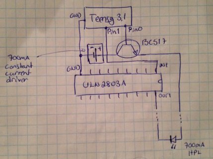
hpl_controller.jpg
Should I use PNP transistors instead to avoid the control current from Pin 0 going through the HPL? I'm newbie with the electronics so spare with me and anything obviously stupid I'm doing :D

Thanks, Jarkko
 
Oh, you've got a few issues here.....

First, is the forward voltage drop across the base to emitter. The BC517 is a darlington transistor, which means it's really 2 NPN transitors in tandem. So the forward voltage will be approx 1.4 volts to get the transistor to fully turn on. Since Teensy 3.1 can drive the base with at most 3.3 volts, the most voltage you'll be able to get at the emitter is about 1.9 volts. When you factor in some voltage drop across the transistor inside the ULN2803, the available voltage won't be enough to turn on even a red LED. It might be able to light up an infrared LED, because those typically need only 1.3 volts.

Another big problem waiting for you is the power dissipation in the BC517. If you did connect an IR LED (and maybe a current measuring device) you'd probably get 0.7 amps of current. But depending on what that power supply does, you could get quite a bit of voltage across the collector to emitter of the BC517. If 0.7 amps flows, that's a lot of power. It could burn that little package very quickly. Or it might be a non-issue, depending on what that constant current power supply does (and how quickly it does it).

Bad things could happen to the Teensy too, since it's connected directly to the base, which is a low impedance path to the emitter.

To make this work, you probably should use a PNP transistor, with its emitter connected to the power supply and its collector connected to the LED anode.

But the trouble with a PNP transistor is how to drive it from the Teensy pin. You'll probably need to use another NPN transistor to turn the PNP on. There are a couple ways to connect this, but the least risky involves connecting the NPN emitter to ground and it's base to Teensy through a resistor. Then connect its collector through a resistor to the PNP base. When Teensy drives the pin high, current will flow from Teensy, through the resistor and into the NPN base. That will turn the NPN on, causing it to pull current from the PNP base. One minor downside is the PNP can be slow to turn off when Teensy turns off the NPN, but usually you can fix that by adding a resistor between the base to emitter of the PNP.
 
Question: would'nt be good mosfets better / more easy ?
There are some types that with VGS below 3 Volt. Can the Teensy drive them directly ?
i remember that i used - long years ago - a bs108(?? or was it another type..hm) with AVR (5V) for a slow PWM
 
Last edited:
Thanks Paul, I'll try the PNP transistor setup. I was thinking of using PN2907 for the PNP since I can buy one from local electronic store and it seems to be able to handle current up to 0.8A. This in conjunction with basic PN2222A NPN transistor. I'm not quite sure what kind of resistors I should use for this setup though, mainly the one between the transistors.

The 0.7A constant current source I'm using is this Super Simple HPL Driver (with 1.8Ohm resistor and LM350) connected to a 9V battery.
 
Resistor values are easy to determine: From the Teensy to the base of the NPN transistor, there will be a voltage drop of ca. 3.3V - 0.6V Ube = 2.7V. Let's drive the base with 2mA, makes 1.35k, choose next standard value 1.5k. From the collector of the NPN transistor to the base of the PNP transistor, there will be a voltage drop of 3.3V - 0.6V Ube - 0.2V Uce = 2.5V. Let's drive that base with 2mA again and add 1 mA to feed the base - emitter resistor = 3mA, makes 833R, choose next standard value 820R. And the base-emitter resistor 0.6V and 1mA = 600R, next standard value 560R. Done.
 
Question: would'nt be good mosfets better / more easy ?
There are some types that with VGS below 3 Volt. Can the Teensy drive them directly ?

The main trouble with mosfets is the gate looks like a huge non-linear capacitor. The more current the mosfet can handle, the higher its gate capacitance is.

For very small mosfets, which have thresholds well under 3V, and where the source terminal is connected to GND (N-Ch) or 3.3V (P-Ch) you can connect them directly. But for mosfets with lower on resistance, the gate becomes too much capacitance. Lower threshold voltage also means the mosfet has higher capacitance. In this project, the source needs to connect to something higher than 3.3V too.

Usually you'd need a special mosfet driver circuit. Those drivers increase the voltage, which lets you use mosfets without such low thresholds, and the driver is able to deliver usually 1 or more amp for the short duration needed to charge or discharge the gate.
 
Status
Not open for further replies.
Back
Top