Maximum GPIO toggling, (Teensy 3.2)

Status
Not open for further replies.

Xenoamor

Well-known member
Hey guys,

I'm looking to use a Teensy 3.2 to write 16 bits of parallel data out at between 10MHz and 40MHz.
To test if this is possible I've written what 'I' think to be the fastest toggling of a pin possible but can only seem to achieve at best 10.3MHz

Code:
void setup() {

	// configure the 8 output pins of Port D
	pinMode(2, OUTPUT);		// #0
	pinMode(14, OUTPUT);	        // #1
	pinMode(7, OUTPUT);		// #2
	pinMode(8, OUTPUT);		// #3
	pinMode(6, OUTPUT);		// #4
	pinMode(20, OUTPUT);	        // #5
	pinMode(21, OUTPUT);	        // #6
	pinMode(5, OUTPUT);		// #7
	GPIOD_PDOR = 0x00000000;
	
	pinMode(pclkInterruptPin, INPUT);
}

void loop() {
	
	noInterrupts();
	clocking();
	
}

FASTRUN static void clocking(void) {
	begin:
		asm (
		
		"mvns %0, %0\n\t"	// Invert Port D
		
		: "+r" (GPIOD_PDOR)
		:
	);
	goto begin;
	
}

This is compiled with -DF_CPU=144000000 and -O3 to produce:
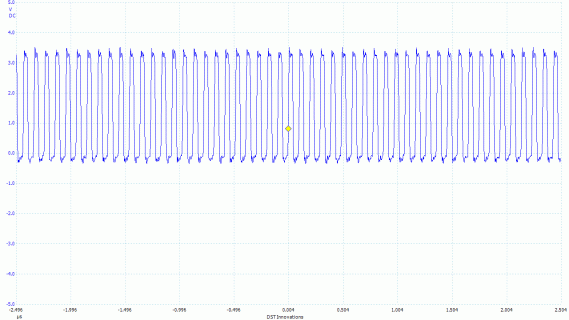
Code:
1fff8760 <_ZL8clockingv>:
1fff8760:	4a02      	ldr	r2, [pc, #8]	; (1fff876c <_ZL8clockingv+0xc>)
1fff8762:	6813      	ldr	r3, [r2, #0]
1fff8764:	43db      	mvns	r3, r3
1fff8766:	6013      	str	r3, [r2, #0]
1fff8768:	e7fb      	b.n	1fff8762 <_ZL8clockingv+0x2>

20151106-0001_01.gif

Am I going about this the wrong way? Or can this be sped up?
 
Last edited:
Is the repeated calling of noInterrupts() in each loop run really necessary?
Can't you "prepare" the data to output before using DMA to write rapidly the port register?
But finally, I fear that outputting parallel data at 40 MHz remains somewhat beyond the Teensy3.x faculties. There have been special SCSI controller chips for that purpose, when I was younger... ;-)

Thanks for the speedy response Theremingenieur!
The function 'clocking' actually is an endless loop so noInterrupts() only gets called the once. I will be using DMA for the real data transfer but for this I am just XORing Port D with 0xFFFFFFFF. This is only one ASM instruction so should be pretty fast for a test.

Looking in more detail 144Mhz/14cycles = 10.29Mhz so this seems to be the magic number which is generating the frequency I'm witnessing. Seems odd that the 5 ASM instructions are 14 cycles though. I'd confirm it but I'm finding it hard to find a detailed documentation for CortexM4 assembly instructions
 
Last edited:
Sorry, didn't see the proprietary loop in the function. Seems that my eyes do "go to" filtering since the ancient BASIC times ;-)
The Cortex M4 reference is here. (From which you can see that ldr takes usually 3 cycles)
Just for my scientific curiosity, since one never knows what this arduino translator deals with the compiler, does it make a difference when you put everything in the setup() and let the loop() empty?
 
Last edited:
Seems like it could be branching to 1fff8764 instead of 1fff8762, did you see what the compiler produced on its own if you just flip the local and set GPIOD_PDOR?
 
This:
Code:
FASTRUN static void clocking(void) {
	begin:
	GPIOD_PDOR ^= 0xFFFFFFFF;
	goto begin;
}

Generates this:
Code:
1fff8760 <_ZL8clockingv>:
1fff8760:	4b02      	ldr	r3, [pc, #8]	; (1fff876c <_ZL8clockingv+0xc>)
1fff8762:	681a      	ldr	r2, [r3, #0]
1fff8764:	43d2      	mvns	r2, r2
1fff8766:	601a      	str	r2, [r3, #0]
1fff8768:	e7fb      	b.n	1fff8762 <_ZL8clockingv+0x2>
1fff876a:	bf00      	nop
1fff876c:	400ff0c0 	andmi	pc, pc, r0, asr #1

Which is exactly the same as my own assembly set.


Why can't I just do this? It seems to mean like it would be significantly faster
Code:
1fff8764:	ea6f 0303 	mvn.w	r3, r3
1fff8768:	f7ff bffc 	b.w	1fff8764 <begin>
The program just hangs and the port never gets toggled. I've also tried subtracting from the PC to skip backwards but the result is the same
 
This:
Code:
FASTRUN static void clocking(void) {
	begin:
	GPIOD_PDOR ^= 0xFFFFFFFF;
	goto begin;
}

What about:

Code:
FASTRUN static void clocking(void) {
        uint32_t toggle = GPIOD_PDOR;
	begin:
        toggle ^= 0xFFFFFFFF;
	GPIOD_PDOR = toggle;
	goto begin;
}

You shouldn't have to read port D because you know what's there, but it's volatile so it can't optimize away the read for you.
 
What about:

Code:
FASTRUN static void clocking(void) {
        uint32_t toggle = GPIOD_PDOR;
	begin:
        toggle ^= 0xFFFFFFFF;
	GPIOD_PDOR = toggle;
	goto begin;
}

You shouldn't have to read port D because you know what's there, but it's volatile so it can't optimize away the read for you.

Thanks for taking the time ecurtz.

Doing so compiles to:
Code:
1fff8760 <_ZL8clockingv>:
1fff8760:	4b02      	ldr	r3, [pc, #8]	; (1fff876c <_ZL8clockingv+0xc>)
1fff8762:	681b      	ldr	r3, [r3, #0]
1fff8764:	4a01      	ldr	r2, [pc, #4]	; (1fff876c <_ZL8clockingv+0xc>)
1fff8766:	43db      	mvns	r3, r3
1fff8768:	6013      	str	r3, [r2, #0]
1fff876a:	e7fc      	b.n	1fff8766 <_ZL8clockingv+0x6>
1fff876c:	400ff0c0 	andmi	pc, pc, r0, asr #1

What you've posted has cut out the LDR command. It'll have to wait until Monday for testing but thank you. It should speed it up by at least two cycles!

EDIT:
I'll have a look into a DMA triggered from an interrupt but I'd be surprised if it's any faster. I'm not too sure what the overheads are for it but I maybe able to stagger the 4 channels to get a fast write/read speed
 
Last edited:
You could double the output speed by using 16 parallel bits and then multiplexing these externally into 2x8... just thinking aloud... :)
 
It's probably best to describe what I'm doing here;

I'm looking to use a MAX9205 LVDS serialiser paired with a MAX9206 deserialiser. On the sending side I'll actually be using something quit beefy, I'm thinking a quad-core Cortex M4 sort of jobby who's role will be to process and stream video.

The deserialisers will be on low cost LED panels. To keep the cost down I'd like to use an MK10/20 for this. So ideally I'm looking to read and process data at 16-45MHz. If I can get the 4 DMA channels working well this should be feasible. I actually have a while to process the data once it's received but it has to be read and stored at those speeds
 
Sorry, didn't see the proprietary loop in the function. Seems that my eyes do "go to" filtering since the ancient BASIC times ;-)
The Cortex M4 reference is here. (From which you can see that ldr takes usually 3 cycles)
Just for my scientific curiosity, since one never knows what this arduino translator deals with the compiler, does it make a difference when you put everything in the setup() and let the loop() empty?

Sorry I seemed to have missed this for some reason...
But thanks, I've bookmarked that reference and printed out the instruction list. I have the feeling I'm going to be using this a lot from here on out.

The arduino main function is as follows:
Code:
#include <Arduino.h>

int main(void)
{
    init();
#if defined(USBCON)
    USBDevice.attach();
#endif
    setup();
    for (;;) {
        loop();
        if (serialEventRun) serialEventRun();
    }
    return 0;
}

As my loop is never ending it can be placed in either setup() or loop() and it will compile exactly the same. The snag is if you let the loop() complete you run the added serialEventRun command which can drop precious clock cycles. Obviously this is needed for serial/usb communication though so it's a trade off as usual
 
Doing so compiles to:
Code:
1fff8760 <_ZL8clockingv>:
1fff8760:	4b02      	ldr	r3, [pc, #8]	; (1fff876c <_ZL8clockingv+0xc>)
1fff8762:	681b      	ldr	r3, [r3, #0]
1fff8764:	4a01      	ldr	r2, [pc, #4]	; (1fff876c <_ZL8clockingv+0xc>)
1fff8766:	43db      	mvns	r3, r3
1fff8768:	6013      	str	r3, [r2, #0]
1fff876a:	e7fc      	b.n	1fff8766 <_ZL8clockingv+0x6>
1fff876c:	400ff0c0 	andmi	pc, pc, r0, asr #1

This yielded 18MHz. I'm not moving over to staggering DMA channels to speed this up.
Cheers for the pointers guys
 
@mortonkopf : thanks, Great! it's exactly what I want, but 32 bit at once is a little annoying :p
 
When changing only some of the bits within a register, don't forget to consider interrupts. If your code reads, modifies and write the register, and so can an interrupt, you need to protect the read-modify-write sequence.
 
Status
Not open for further replies.
Back
Top