Nominal Animal
Well-known member
As you probably know, ground loops (ground potential differences) are a frequent headache when using a Teensy to interface to external hardware. The computer the Teensy is connected to, and the external hardware Teensy interfaces to, are rarely using the same ground potential. In my case, the peripherals are 5 VDC (GPIB aka IEEE-488 bus transceivers to interface to oscilloscopes and such). I do believe the audio folks encounter this often, too.
It occurred to me that 5 VDC regulated wall-warts are ubiquitous, and the safe ones are galvanically isolated. To avoid the ground loop via USB ground, an USB isolator chip like Analog Devices ADuM3160 (datasheet) can be used to galvanically isolate the Teensy from the USB bus. A 3.3 VDC low drop-out voltage regulator (like Microchip MCP1726; datasheet) can be used for 3.3 V peripherals, ADuM3160 (although slightly different wiring compared to below), and the Teensy itself.
In my case, Teensy will be the only one using 3.3 V, so I'm looking at using a buck-boost DC-DC regulator like Texas Instruments TPS63061 (datasheet) that can take a DC voltage between 2.5 V and 12 V, and provide a nicely regulated 5V supply and enough current (1.4 A, if the wall-wart supplies enough current) to power the Teensy, USB isolator, and peripherals (like SN75160 and SN75162 GPIB/IEEE-488 transceivers in my case).
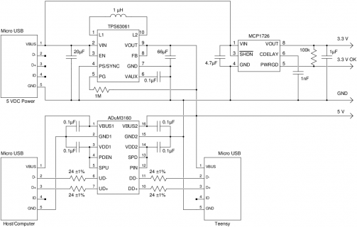
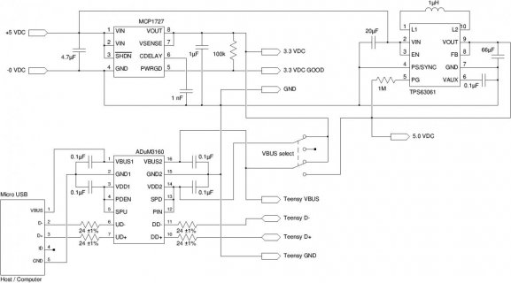
Unfortunately, my EE-fu is weak. I have checked the suggested/typical use circuits, and the resulting schematic looks suspiciously simple to me. Here, I've fixed the ADuM3160 for full-speed operation (12Mbit/s), and supply Teensy with 5V using the USB connector. Although I won't be using it, I've included the 3.3V regulator (MCP1726) in the upper right corner.

As I mentioned, for 3.3V only operation, the TPS63061 can be left out, but then the ADuM3160 should be wired slightly differently, as indicated in the datasheet. Remember: the above circuit assumes the USB power is supplied by a galvanically isolated supply.
My intention is to put this onto a small additional board. I'd prefer to cannibalize a USB-to-micro-USB cable, so that I could use the last 1" or so to connect the board to the Teensy (allowing for easy inclusion within different enclosure types), and use the rest as a built-in USB cable to the computer -- thus, just through-holes for the wires, no connectors on board.
Since something like this is so often needed, I'm certain I'm not the only one looking at such a circuit.
Could you (anyone?) help with the design of such a board? If you have experience with ADuM3160, could you check if I've missed anything obvious in the schematic above?
(I've omitted the ADuM3160 datasheet suggestions for actual capacitor, inductor, and resistor types. Also, it might be very useful to have two variants of the board, the other with just 3.3V needed -- avoiding the expensive buck-boost converter, using just a 3.3V LDO regulator instead.)
The above can be the starting point. I'm happy with any open/free license for such a design. This is very specific to Teensy, and the use case is a bit weird, because end-users must be told to use specific USB wall warts for power supply (as opposed to, say, connecting a second USB from the computer). It might actually make sense to use a DC21 or DC25 power jack for the 5V input DC power, instead of a micro-USB connector (upper left corner of the schematic).
Comments? Suggestions?
It occurred to me that 5 VDC regulated wall-warts are ubiquitous, and the safe ones are galvanically isolated. To avoid the ground loop via USB ground, an USB isolator chip like Analog Devices ADuM3160 (datasheet) can be used to galvanically isolate the Teensy from the USB bus. A 3.3 VDC low drop-out voltage regulator (like Microchip MCP1726; datasheet) can be used for 3.3 V peripherals, ADuM3160 (although slightly different wiring compared to below), and the Teensy itself.
In my case, Teensy will be the only one using 3.3 V, so I'm looking at using a buck-boost DC-DC regulator like Texas Instruments TPS63061 (datasheet) that can take a DC voltage between 2.5 V and 12 V, and provide a nicely regulated 5V supply and enough current (1.4 A, if the wall-wart supplies enough current) to power the Teensy, USB isolator, and peripherals (like SN75160 and SN75162 GPIB/IEEE-488 transceivers in my case).
Unfortunately, my EE-fu is weak. I have checked the suggested/typical use circuits, and the resulting schematic looks suspiciously simple to me. Here, I've fixed the ADuM3160 for full-speed operation (12Mbit/s), and supply Teensy with 5V using the USB connector. Although I won't be using it, I've included the 3.3V regulator (MCP1726) in the upper right corner.

As I mentioned, for 3.3V only operation, the TPS63061 can be left out, but then the ADuM3160 should be wired slightly differently, as indicated in the datasheet. Remember: the above circuit assumes the USB power is supplied by a galvanically isolated supply.
My intention is to put this onto a small additional board. I'd prefer to cannibalize a USB-to-micro-USB cable, so that I could use the last 1" or so to connect the board to the Teensy (allowing for easy inclusion within different enclosure types), and use the rest as a built-in USB cable to the computer -- thus, just through-holes for the wires, no connectors on board.
Since something like this is so often needed, I'm certain I'm not the only one looking at such a circuit.
Could you (anyone?) help with the design of such a board? If you have experience with ADuM3160, could you check if I've missed anything obvious in the schematic above?
(I've omitted the ADuM3160 datasheet suggestions for actual capacitor, inductor, and resistor types. Also, it might be very useful to have two variants of the board, the other with just 3.3V needed -- avoiding the expensive buck-boost converter, using just a 3.3V LDO regulator instead.)
The above can be the starting point. I'm happy with any open/free license for such a design. This is very specific to Teensy, and the use case is a bit weird, because end-users must be told to use specific USB wall warts for power supply (as opposed to, say, connecting a second USB from the computer). It might actually make sense to use a DC21 or DC25 power jack for the 5V input DC power, instead of a micro-USB connector (upper left corner of the schematic).
Comments? Suggestions?


