Audio Lib & OctoWS2811 Lib & Hardware?

Status
Not open for further replies.
I have searched the forum a number of times in the last 2 weeks.
I found something from Nov 2014 talking about the audio library and the OctoWS2811 library.
And an issue with the DMA channels conflicting.

Ok so the questions are
1 Will the Audio shield and the OctoWS2811 shield work with each other?
(I see a hardware conflict with pins for the SD card)
2 Will the Audio library and the OctoWS2811 library work to gather without the SD?

Thanks all in advance!
GeckospotNixie
 
I've been meaning to write a page about this. Somehow it keeps getting push aside by more urgent stuff.

In a nutshell, it should be possible to run both of these, with a little extra code. The main issue is OctoWS2811 will reassign some of the pins the audio shield needs in I2S mode to be GPIO, which it controls by DMA. After starting OctoWS2811, those pins will need to reconfigured back to control by I2S.

Likewise, OctoWS2811 and SPI can conflict, if the SPI pins are reassigned as the audio shield needs. If you're going to use a SD card, those will also need similar code.

Really, what I need to do is put some serious time into getting this running here with the audio board and octo board and the 1920 LEDs.... and of course take photos and write it up. That takes significant time to do well. It's on my list, really.... but there's a few other really high priority things going on here too, so this is going to keep getting pushed back for a while. Sorry.
 
Thanks for the reply Paul!
Thanks Thialf I did see that post but it is just SD not full Audio shield.

I think that for now i will use two Teensy one for audio and one for the OctoWS2811 and transfer the data from audio to the other.
 
If you wire the SD card with the normal connections: MOSI to 11, MISO to 12, SCK to 13, and SS to an unused digital pin; there is no conflict with OctoWS2811. All you have to do is connect wire so the MOSI and SCK signals go to 11 and 13, rather than 7 and 14.

But if using the VideoDisplay example, delete the stuff for sync on pin 12, since MISO uses that pin.
 
Obviously, for the audio shield pins that do conflict with OctoWS2811, simply don't connect those wires between the audio shield and Teensy+octo shield. This is pretty simple if you're just using the SD card portion.
 
Pjrc products are outstanding! Thank You Paul!

This progress I have made.
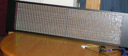
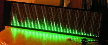
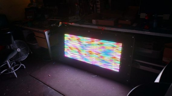
Over the holidays I built an OctoWS2811 display board.
It is not too big it is 60 by 24 so 1 meter by 260mm.
So that comes out to be 1440 WS2812B LEDs.
The goal is to use the OctoWB2811 and the WB2812B display as an audio spectrum analyzer.

WB2812B Light.JPG WB2812B Dark WEB.JPG

I started out using the A3 ADC input and the basic spectrum analyzer sketch from the OctoWB2811 example folder. The performance of the ADC input and the example circuitry is not the best in the full audio spectrum
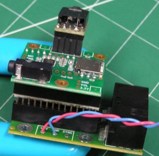
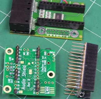
So I figured out what pins on the Audio Shield that I would be able to interface to the Teensy and OctoWB2811 without impacting any of the OctoWB2811 function.
What I have interfaced from the Audio Shield to the Teensy 3.2 and then the OctoWB2811 shield are pins 23, 22, 19, 18, 11, 13, 9 and of course the 3.3Vand the ground pins.
The basic sketch listed below uses the line input a mixer and the FFT1024 of the Audio library (using the outstanding Audio System Design Tool).

Shields Stacked.JPG Shields.JPG

Code:
// LED Audio Spectrum Analyzer Display
// 
// Creates an impressive LED light show to music input
//   using Teensy 3.1 with the OctoWS2811 adaptor board
//   http://www.pjrc.com/store/teensy31.html
//   http://www.pjrc.com/store/octo28_adaptor.html
//
// Line Level Audio Input connects to analog pin A3
//   Recommended input circuit:
//   http://www.pjrc.com/teensy/gui/?info=AudioInputAnalog
//
// This example code is in the public domain.


#include <OctoWS2811.h>
#include <Audio.h>
#include <Wire.h>
#include <SD.h>
#include <SPI.h>
#include <SerialFlash.h>

// The display size and color to use
const unsigned int matrix_width = 60;
const unsigned int matrix_height = 24;
const unsigned int myColor = 0x000700;    // 1/16 Power Green

// These parameters adjust the vertical thresholds
const float maxLevel = 0.4;      // 1.0 = max, lower is more "sensitive" Oraignal .5 then .3
const float dynamicRange = 40.0; // total range to display, in decibels
const float linearBlend = 0.3;   // useful range is 0 to 0.7


AudioControlSGTL5000 audioShield;

// GUItool: begin automatically generated code
AudioInputI2S            i2s1;           //xy=217,220
AudioMixer4              mixer1;         //xy=369,319
AudioAnalyzeFFT1024      fft;            //xy=509,319  fft1024_1
AudioConnection          patchCord1(i2s1, 0, mixer1, 0);
AudioConnection          patchCord2(i2s1, 1, mixer1, 1);
AudioConnection          patchCord3(mixer1, fft);
AudioControlSGTL5000     sgtl5000_1;     //xy=341,406


// OctoWS2811 objects
const int ledsPerPin = matrix_width * matrix_height / 8;
DMAMEM int displayMemory[ledsPerPin * 6];
int drawingMemory[ledsPerPin * 6];
const int config = WS2811_GRB | WS2811_800kHz;
OctoWS2811 leds(ledsPerPin, displayMemory, drawingMemory, config);

// This array holds the volume level (0 to 1.0) for each
// vertical pixel to turn on.  Computed in setup() using
// the 3 parameters above.
float thresholdVertical[matrix_height];

// This array specifies how many of the FFT frequency bin
// to use for each horizontal pixel.  Because humans hear
// in octaves and FFT bins are linear, the low frequencies
// use a small number of bins, higher frequencies use more.
int frequencyBinsHorizontal[matrix_width] = {
   1,  1,  1,  1,  1,  1,  1,  1,  1,  1,
   2,  2,  2,  2,  2,  2,  2,  2,  2,  3,
   3,  3,  3,  3,  4,  4,  4,  4,  4,  5,
   5,  5,  6,  6,  6,  7,  7,  7,  8,  8,
   9,  9, 10, 10, 11, 12, 12, 13, 14, 15,
  15, 16, 17, 18, 19, 20, 22, 23, 24, 25
};


// Run setup once
void setup() {
  // the audio library needs to be given memory to start working
  AudioMemory(12);

  // Enable the audio shield and set the output volume.
  audioShield.enable();
  audioShield.inputSelect(AUDIO_INPUT_LINEIN);
  audioShield.lineInLevel(6);
  

  // compute the vertical thresholds before starting
  computeVerticalLevels();
  
  //fft.windowFunction(AudioWindowTukey1024);
  //fft.windowFunction(AudioWindowBlackmanHarris1024);

  // turn on the display
  leds.begin();
  leds.show();
}

// A simple xy() function to turn display matrix coordinates
// into the index numbers OctoWS2811 requires.  If your LEDs
// are arranged differently, edit this code...
unsigned int xy(unsigned int x, unsigned int y) {
  if ((y & 1) == 0) {
    // even numbered rows (0, 2, 4...) are left to right
    return y * matrix_width + x;
  } else {
    // odd numbered rows (1, 3, 5...) are right to left
    return y * matrix_width + matrix_width - 1 - x;
  }
}
//unsigned int xy(unsigned int x, unsigned int y) {
//    return y * matrix_width + x; //All rows Left to Right
//}

// Run repetitively
void loop() {
  unsigned int x, y, freqBin;
  float level;

  if (fft.available()) {
    // freqBin counts which FFT frequency data has been used,
    // starting at low frequency
    freqBin = 0;

    for (x=0; x < matrix_width; x++) {
      // get the volume for each horizontal pixel position
      level = fft.read(freqBin, freqBin + frequencyBinsHorizontal[x] - 1);

      // uncomment to see the spectrum in Arduino's Serial Monitor
      // Serial.print(level);
      // Serial.print("  ");

      for (y=0; y < matrix_height; y++) {
        // for each vertical pixel, check if above the threshold
        // and turn the LED on or off
        if (level >= thresholdVertical[y]) {
          leds.setPixel(xy(x, y), myColor);
        } else {
          leds.setPixel(xy(x, y), 0x000000);
        }
      }
      // increment the frequency bin count, so we display
      // low to higher frequency from left to right
      freqBin = freqBin + frequencyBinsHorizontal[x];
    }
    // after all pixels set, show them all at the same instant
    leds.show();
    // Serial.println();
  }
}


// Run once from setup, the compute the vertical levels
void computeVerticalLevels() {
  unsigned int y;
  float n, logLevel, linearLevel;

  for (y=0; y < matrix_height; y++) {
    n = (float)y / (float)(matrix_height - 1);
    logLevel = pow10f(n * -1.0 * (dynamicRange / 20.0));
    linearLevel = 1.0 - n;
    linearLevel = linearLevel * linearBlend;
    logLevel = logLevel * (1.0 - linearBlend);
    thresholdVertical[y] = (logLevel + linearLevel) * maxLevel;
  }
}

The Audio Shield line input is by far superior to the ADC input. The performance is really outstanding through out the full audio spectrum and especially at the higher frequencies.

I tried having an I2S output making the spectrum analyzer a pass thru device that would have some audio enrichments like Bass boost but the I2S out would not work with OctoWB2811.
I would only get one funny looking display when I first turned on the system. I'm sure that with the 3 DMA channels from the OctoWB2811 the one on the I2S linein and the one on the I2S lineout that there is a conflict.
I looked at the DMA code in all the objects and read the FreeScale MK20 DMA section but I was just not picking up the full picture vary fast so I moved on (I will need to study this some more).
So I removed the I2S output making the spectrum analyzer input only and this worked with out any issues.

Paul
This is about the fifth time I have used the Teensy in a project and have never been let down yet!
You have outstanding products!
And excellent software!
Thank YOU

GeckospotNixie
 
Nice work Gecko, I am going to give this set-up a spin but with FastLED library. A bump to Paul, I'd love to see you tackle this and a write-up as well (maybe now that the 3.5 / 3.6 release is over? hint hint :) )
 
Nice work Gecko, I am going to give this set-up a spin but with FastLED library. A bump to Paul, I'd love to see you tackle this and a write-up as well (maybe now that the 3.5 / 3.6 release is over? hint hint :) )
 
Where did you get the 14x1 sockets with long pins? Where did you get the audio jack? I have a light board I built, It's already works using the OctoWS2811. It uses sockets, so I was thinking this would be an easy upgrade with your (very nice) write up. If anyone has a source for these two parts, I'm all ears...
IMG_20180620_043317428_HDR.jpg
 
The 1x14 header / sockets are from Adafruit or maybe Paul (PJRC) don’t remember.
But I'm sure there where longer and I cut them to 14s.
The audio jack is just some PCB a jack and header pins.
 
I've just tried this and I can get the audio board and octo board to work independently but not together. I have duplicated the octo board pins as shown in the photo above but I get nothing on the strip. The only difference I have is that I use a different combination of pin and socket headers. Is there something else that needs doing?

Ta.

I can only help if your using all PJRC hardware.
I need some more information to work with here.
Are you using all PJRC hardware?

What Teensy are you trying to use? (I used a Teensy 3.2, not sure this will work with anything else.)

Can you post photo of your setup? (It would help a lot.)

GeckospotNixie
 
Solved!

I can only help if your using all PJRC hardware.
I need some more information to work with here.
Are you using all PJRC hardware?

What Teensy are you trying to use? (I used a Teensy 3.2, not sure this will work with anything else.)

Can you post photo of your setup? (It would help a lot.)

GeckospotNixie

Thanks, I figured it out.

The first problem was that my LED strip is longer than I thought. After figuring this out I could get the wipe function to work. I still couldn't set individual leds at the start of the strip. The second was that it was plugged into the wrong socket - I'm only using one strip at the moment. Finally, there was a lack of understanding of the OctoWS2811 methods.

The BasicTest example used a method numPixels, which I couldn't find documented. This, I think, is 8 * the LED strip length so no matter which ethernet pair was used, using this in the wipe function will light up the strip. Not seeing individual LED settings was because the strip was plugged into the wrong socket. Reading through the API I got the impression that each strip would be addressed separately but I don't think that's the case any more since there is only one constructor called. I just haven't figured out how different lengths can be used, not that I'll be using different lengths.

I've converted the code I used for my MSGEQ7 setup and it works well now. I haven't broken the strip up but I now have something scaleable so the next step is to buy a few more strips and set up a panel. I'm using FFT256 so I can have stereo displays and cycle between spectrum analyser and VU type displays. I think I'll try and write a class rather than the structured code I've used so far. I took some video of it but don't know whether I can post that here.

In any case, this thread has helped enormously because I would have just tried connecting everything between the audio shield and the OctoWS2811 board. Luckily I did the research beforehand.

Many thanks.
 
Thank you @GeckospotNixie and @alidaf for the helpful information, can't believe the timeliness of this post...I'm about to start a similar project.

Would either of you be able to post a circuit diagram of the setup as well? I know they would essentially convey the same information as the pictures posted but it helps for a beginner like me to see an overall schematic.

Thanks in advance and good luck on any future projects!
 
I typically host my code on github and have ascii art circuit diagrams in the header file or a circuit.txt file so that it all becomes a good learning guide for anyone, as well as myself. I threw this together from code I used for an MSGEQ7 project so haven't done the diagrams yet but I will do and it should appear on my github site, probably under Arduino unless I create a Teensy repo. Just give me a few days because I can get very obsessive about them. Also be aware that I still have a single continuous LED strip so the bands are one after the other. In a matrix the layout will be a bit different but I have just derived the mapping for having a more typical grid with the intention of re-writing it all as a class.
 
I've had a quick stab at this during work. It may change a bit but I think the essentials are in.

The pin connections are as specified by GeckospotNixie but some of them might still be unnecessary depending on the inputs you are using, i.e. pins 0, 1, 10, 17 and AGND. I thought it was safer to just use what someone had already demonstrated to work. I'm only using line level inputs but some of these pins may be needed for ADC input.

Hope it helps but please proceed with caution as it hasn't been verified.

Code:
/* -----------------------------------------------------------------------------

    Circuit diagram for Teensy/Audio shield/OctoWS2811 spectrum analyser.

    Note: The audio shield and OctoWS2811 shield weren't designed to work
          together but by avoiding specific connections, the two will
          work although without the functionality of the SD card slot on the
          audio shield. A combination of stackable headers and pins can be
          used with the specific connections made on the audio shield as
          follows:

                    .....  .......
    Audio shield   ================  Inverted socket headers
                    nnnnn  nnnnnnn

                    ..............
    Teensy      USB================  Pins soldered on the long side.
                    ||||||||||||||
                                    ,----,
                                    |    |
                    uuuuuuuuuuuuuu  |    |
    OctoWS2811     ======================= Stackable female headers.
                    ''''''''''''''

    o connected
    x not connected

    Audio shield:     Teensy:          OctoWS211:

    o GND  5V o       o GND  5V o      o GND  5V o
    o 0     G o       o 0     G o      o 0     G o
    o 1    3V o       o 1    3V o      o 1    3V o
    x 2    23 o       o 2    23 o      o 2    23 o
    x 3    22 o       o 3    22 o      o 3    22 o
    x 4    21 x       o 4    21 o      o 4    21 o
    x 5    20 x       o 5    20 o      o 5    20 o
    x 6    19 o       o 6    19 o      o 6    19 o
    x 7    18 o       o 7    18 o      o 7    18 o
    x 8    17 o       o 8    17 o      o 8    17 o
    o 9    16 x       o 9    16 o      o 9    16 o
    o 10   15 x       o 10   15 o      o 10   15 o
    o 11   14 x       o 11   14 o      o 11   14 o
    x 12   13 o       o 12   13 o      o 12   13 o


    All power supply and LED connections are on the OctoWS2811 board.

    Note: The external power supply and the 5V USB supply must 
          be decoupled if connected at the same time otherwise 
          the USB may be backpowered. This is done by severing
          the bridge on the Teensy. See the advice at
          https://www.pjrc.com/teensy/td_libs_OctoWS2811.html Section
          Teensy 3.0 Power.
          Unfortunately this means that the external power supply needs to be
          connected in order to program the Teensy.

          The LED numbering is contiguous and based on the method
          constructor that requires the number of LEDs per strip to
          be passed as a parameter. 
          See https://www.pjrc.com/teensy/td_libs_OctoWS2811.html

          n = number of LEDs per strip.
          
    Power supply                OctoWS2811 power terminal
      +5V GND                  +5V GND SYNC
       o   o                    o   o   x
       |   |                    |   |
       |   '--------------------(---| GND should be as close to the LED
       '------------------------|   | GND connection as possible.
                                |   |
     Ethernet sockets           |   |
    ,-----------------,         |   |
    |                 |         |---(------------o +5V
    | 1 Orange        o---------(---(------------o Data (LED 0 -> n-1)
    |   White/Orange  o---------(---+------------o GND
    |                 |         |   |
    |                 |         |---(------------o +5V
    | 2 Blue          o---------(---(------------o Data (LED n -> 2n-1)
    |   White/Blue    o---------(---+------------o GND  
    |                 |         |   |
    |                 |         |---(------------o +5V
    | 3 Green         o---------(---(------------o Data (LED 2n -> 3n-1)
    |   White/Green   o---------(---+------------o GND   
    |                 |         |   |
    |                 |         |---(------------o +5V
    | 4 Brown         o---------(---(------------o Data (LED 3n -> 4n-1)
    |   White/Brown   o---------(---+------------o GND   
    |                 |         |   |
    |-----------------|         |   |
    |                 |         |---(------------o +5V
    | 5 Orange        o---------(---(------------o Data (LED 4n -> 5n-1)
    |   White/Orange  o---------(---+------------o GND
    |                 |         |   |
    |                 |         |---(------------o +5V
    | 6 Blue          o---------(---(------------o Data (LED 5n -> 6n-1)
    |   White/Blue    o---------(---+------------o GND  
    |                 |         |   |
    |                 |         |---(------------o +5V
    | 7 Green         o---------(---(------------o Data (LED 6n -> 7n-1)
    |   White/Green   o---------(---+------------o GND   
    |                 |         |   |
    |                 |         '---(------------o +5V
    | 8 Brown         o-------------(------------o Data (LED 7n -> 8n-1)
    |   White/Brown   o-------------+------------o GND   
    |                 |
    '-----------------'

    Note: Multiple power supplies may be needed if there are a lot of LEDs.
          A good guide to calculating power requirements is here...
          https://docs.audectra.com/guides/hardware/led-power-consumption/

          I am currently running a 5m 240 led strip with a 60W supply.

*/ -----------------------------------------------------------------------------
 
Last edited:
Status
Not open for further replies.
Back
Top