USB Connectivity on custom Board

Status
Not open for further replies.

nemation

Active member
Hi there....

so i finally managed to get a NEARLY working PCB in the 4th. Version ;-)
No more burned Chips, working Bootloader.... but still hanging on the USB connectivity.

Everything seems to work fine. When pressing reset, Windows finds a new USB device - but is not able to
identify it. (no PID etc)
After some research, i think my USB Design is really bad ;-)

But i have two questions here -
is there any chance to bypass the problem, for example with slowing down USB speed ?
I soldered some wires from the VIA's below the MK20 to the resistors of the USB Connection, but no change.

Could this issue be caused by something else than the USB Layout ?
i don't want to build another Prototype, only to see, that the error is somewhere else ;-)

best regards,
Henning

board.jpg
 
is there any chance to bypass the problem, for example with slowing down USB speed ?

No. The USB speed is fixed at 12 Mbit/sec. 1.5 Mbit/sec is not supported.

Could this issue be caused by something else than the USB Layout ?

The layout for 12 Mbit/sec USB is not really critical. The crystal is the only highly sensitive part of this design, in terms of physical layout.

However, wiring errors will ruin any design. I suppose that's also a layout mistake, but very different from correct wiring with non-optimal physical placement.

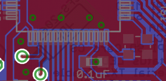
I looked at this image for a few moments. I don't understand how the power and ground lines connect. Is it a 4 layer PCB?
 
O, i see... i forgot to activate the GND / 3V Planes in the View. New Image attached.

Windows doesn't find the device - i only can heer the Sound when plugged in. It tells me, the device is not working. In the hardware Manager i can see, that there is a device, but no PID submitted.
lsusb in linux seems to find nothing.

board2.jpg
 
Have you checked the ground and power planes? Does ground really connect to all locations ground?

With the power off and all wires disconnected, try using a multimeter in ohms mode. Use the highest range, if not an auto-ranging meter... do not use the beeper mode. Physically measure from the USB connector to every other ground location on the PCB. Are they all really zero ohms?
 
Just checked the Ground Planes / Powerplanes. Everything seems to be as it should be. (or at least, what i think should be ;-))
they all show 0.8 Ohms. As this is the same value i get, when i shorten the probes of the multimeter, this should be ok.

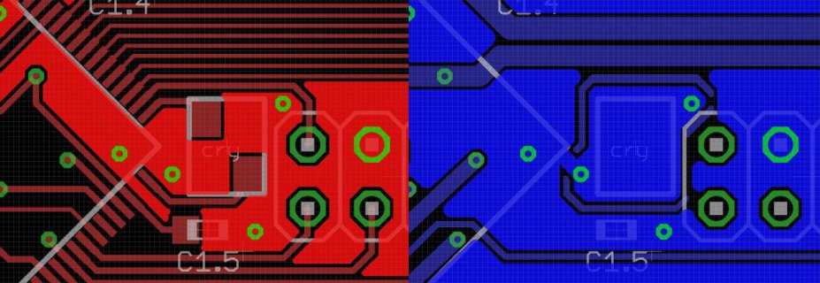
I'm not really sure if i unterstood right, of to layout the crystal. I Just added a closeup from the upper side and the lower side (blue) of the pcb.

But when i understood right, the crystal is not used on startup - or does it cange when i press the reset button ?

crystal.jpg
 
I'll just chime in, and note that USB data lines should be kept in parallel (in Eagle you can 'link' two traces by labeling one _N and one _P, I believe). There's also a function to add a little bit of length to only one side of this differential dual-trace, so that both traces are the exact same length. At high speeds, a trace that's dramatically longer than the other can cause very strange issues. Things like changing the tracewidth only on parts of the data path, and vias can also cause big problems. Basically, you should try and route your USB data traces together, almost as if they were a single trace.

Because of the way USB sends data (on one trace it has the data, and on the other it has the inverse of that data, so a 0 on one is a 1 on the other), having the two traces 'out of sync' due to one being longer, and thus delaying one half of the signal slightly, can cause bits to be lost or interpreted incorrectly.

Now, I say all this, but I expect that your board is too small for this to really be the root of the issue - just something you should be aware of, and in your next revision of the board I'd highly recommend trying to follow it. Can't hurt, right?
 
Any minor point to consider is thermal relief on the pads to ground. You've got ground flooding over every GND pin. Electrically that's fine. For hand soldering, it makes good solder joints quite difficult. You have to apply a lot of heat. Most parts can take the heat, but the practical risk is if you don't get enough heat you can end up with a "cold solder" joint which looks reasonable, but conducts poorly or not at all.

But when i understood right, the crystal is not used on startup - or does it cange when i press the reset button ?

The crystal does not automatically start. The MK20 begins running code using an internal oscillator. Software has to turn on the crystal and wait for it to become stable before switching the CPU to use it. Details can be found in the MCG and OSC chapters of the MK20 reference manual, or in mk20dx128.c inside hardware/teensy/avr/cores/teensy3.
 
Just checked the Ground Planes / Powerplanes. Everything seems to be as it should be. (or at least, what i think should be ;-))
they all show 0.8 Ohms. As this is the same value i get, when i shorten the probes of the multimeter, this should be ok.

FWIW, that's not how I design my powerplanes around the crystal. Under the crystal I have an unbroken GND plane. The GND area around the crystal is isolated from other GND planes except where it connects to the GND plane under the MCU. Thus, the only currents that run in there are related to the crystal.

pcb-top.gif
 
GK, thanks for all the tipps so far.
As i got a bit fed up with only using a multimeter, i went out to buy a new toy.
I started to compare my Board with a working Teens - i've set them both to the "program" Mode.
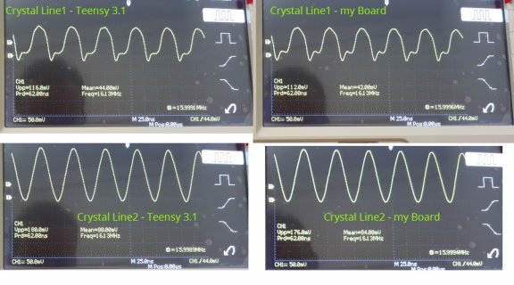
At first, i checked the crystal - seems good so far:
chart1.jpg

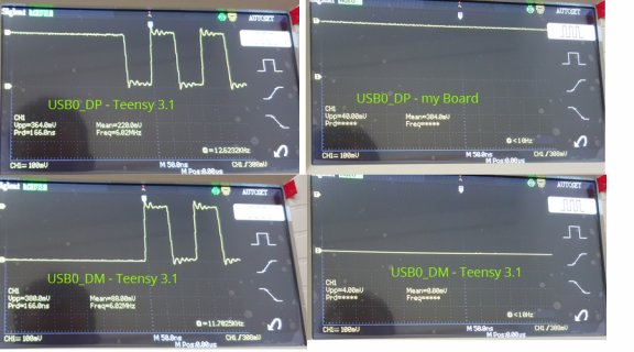
After that, i had a look at The USB0_DP and the USB0_DM lines. Both boards showed the same result.
Then i plugged them into a PC:

chart2.jpg

I assume, the MK20 shoud do something when connected, but it doesn't.

One moment.... before i post this, i'll check the PTA1 Line.....

(some mintes later)

ok. nothing special. both show me 3.3V.
(i just saw, teensy has a freq of 538 KHz on PTA1 where my board has a Freq. of 783 KHz ?!)

Ok. My Board is not talking to the PC.
From where is the information coming, that the board is connected to the PC ? PTA1 ? Or should the PC send
some information over the two USB0 lines ?

best regards,
Henning

@Paul: Eagle offers the Themals by Standard, as i use a small oven for soldering,
this should not be an issue - at least, that's what i thought ;-)
 
Status
Not open for further replies.
Back
Top