Analog input protection

Status
Not open for further replies.

syntesys

Member
Hi all,

I'm building a guitar midi footswitch with an external expression pedal plugged to the board with a jack cable. I saw that when I connect the jack when the board is working, all the times the board reset (maybe due to the 3.3v pin short circuit with the analog pin). How can I avoid that?

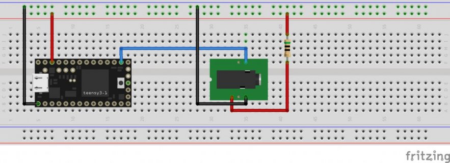
The schematic is attached.

Thank you all.
Jack sketch.jpg
 
If what you mean is that it works unplugged and works plugged but moving the plug in operation kills things then I'd say have a look at what happens as you slide the connector into that jack.

It appears to by a stereo audio jack, if so you have the analog on the tip, then +3.3 then ground. Either the tip or the inner ring is bridging as you slide the plug in. If you can I'd suggest re-designing so that +3.3 is the one deepest inside the jack, and analog in in the middle, then as you slide the plug in you'll always have a ground present, and while the analog may get misconnected as it goes in it's unlikely (though not technically impossible) that power and ground will bridge. As a safety net would suggest a 50ohm resistor in series with the +3.3V, which would constrain current in this case, and any mishaps in the pedal during use.

It's fortunate that the regulator has survived.
 
If what you mean is that it works unplugged and works plugged but moving the plug in operation kills things then I'd say have a look at what happens as you slide the connector into that jack.

Yes, is that.

It appears to by a stereo audio jack, if so you have the analog on the tip, then +3.3 then ground. Either the tip or the inner ring is bridging as you slide the plug in. If you can I'd suggest re-designing so that +3.3 is the one deepest inside the jack, and analog in in the middle, then as you slide the plug in you'll always have a ground present, and while the analog may get misconnected as it goes in it's unlikely (though not technically impossible) that power and ground will bridge. As a safety net would suggest a 50ohm resistor in series with the +3.3V, which would constrain current in this case, and any mishaps in the pedal during use.

It's fortunate that the regulator has survived.

As I can see, the regulator is very strong, because I had lots of reset without problems.

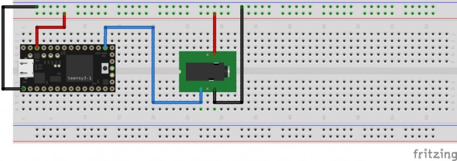
So, this will be the new circuit?
JackCorrected_bb.jpg

Thank you.
 
If that puts the pins in the right place, but suggest testing with your actual connector since not all of them have pins in logical places. Adding the resistor will cut the top end out of the analog read range, but assuming a 1 or 10K pot in the pedal should only be a small fraction of the range, for a greatly reduced chance of problems.
 
I'd go with a 100 ohm resistor (the colors look like 50 ohms). Yes, it'll cut off a tiny bit more of your range, but that's simple to fix in software.
 
Good morning!
I put the 100 ohm resistor but I don't know now how to fix the range in software... Can anyone help me???
 
Do you currently have working code to translate the analog range of the expression pedal to MIDI? If so, you should post it. It may be as simple as changing a "1023" to a "1011" (that's the max analog I get with a 100 ohm resistor). Use "Examples/Teensy/Tutorial4/AnalogInput" to be sure.
 
Status
Not open for further replies.
Back
Top