impossible constraint in 'asm'

Status
Not open for further replies.

agys

Member
Hello to everybody,

I just got my first Teensy 3.2 board and I'm loving it so far.
I have some experience with Arduino and I'm trying to port a project to the Teensy especially for it's extra memory.
I'm driving a VFD display from Noritake and I'm using their library which contains a small asm part…
When I try to compile it for the Teensy it get this error:

impossible constraint in 'asm'

The complete function:
Code:
static inline void tunedDelay(uint16_t delay){
  uint8_t tmp=0;

  asm volatile("sbiw    %0, 0x01 \n\t"
	"ldi %1, 0xFF \n\t"
	"cpi %A0, 0xFF \n\t"
	"cpc %B0, %1 \n\t"
	"brne .-10 \n\t"
	: "+r" (delay), "+a" (tmp)
	: "0" (delay)
	);
}

The complete library can be found here:
https://www.noritake-elec.com/specification.php?id=Arduino_Noritake_VFD_CUY&category=10&type=cuy

Many thanks for eventual help!
 
Well..this is assembler for AVR. You can't use that for Teensy 3 ! The Teensy 3 uses an ARM cpu.
The good news is, that it seems to be a delay - perhaps you can replace the assemblercode with simply calling "delayMicroseconds() " ?
Maybe it's needed to adjust the "delay" value, then.
I don't know how long the code above waits.


Simply try:
Code:
static inline void tunedDelay([B]const [/B]uint16_t delay){
 delayMicroseconds(delay);
}
If that does not work, it may be too fast, then try delay*10 or similar..


Perhaps there is a measuring of the loop-time somewhere else in the code, the name " tunedDelay" indicates that.


Last edited:
Frank & Paul, thank you very much for your input!

I recompiled the project and as the asm portion has been substituted with the regular delay function it doesn't throw any error.
I wonder why the original author(s) rewrote it? Maybe for precision? It seems to me that the value passed as argument is small… (14 or more).

I can't test the display (yet) because it's running on 5V…
I hoped that maybe the logic would work anyway but it doesn't.
I'll try with a level converter… Updates will follow!
 
Frank & Paul, thank you very much for your input!

I recompiled the project and as the asm portion has been substituted with the regular delay function it doesn't throw any error.
I wonder why the original author(s) rewrote it? Maybe for precision? It seems to me that the value passed as argument is small… (14 or more).
I imagine it might be due to AVR's being slow. And for small values of delay, the overhead of calling a function and returning from it might skew the actual delay.
 
I imagine it might be due to AVR's being slow. And for small values of delay, the overhead of calling a function and returning from it might skew the actual delay.

I can confirm this.
You can't get a 5 clock delay or less as you'll spend that getting in and out of a function. Using an inline function is a concise way of doing this.
 
I can confirm this.
You can't get a 5 clock delay or less as you'll spend that getting in and out of a function. Using an inline function is a concise way of doing this.

They had the same issue with the DHT22 sensor. The AVR version of the code features a 1-us delay, knowing that in real life the AVR will not manage anything shorter than 5us. Use that code on a Teensy and the Teensy times out because the 1us delay is actually done correctly.
 
Hi folks. First off, apologies for resurrecting an old thread like this, but I'm dealing with a very similar issue and cannot find much info out there. Some of this thread is pertinent.

I'm trying to get a Noritake GU-7000 series VFD (it's a graphic one, 140x32 dots) to work with a Teensy 3.5, but not having much success after hours spent on it. Maybe someone here could see something I'm not.

- First off, I am able to use this module without an issue on an Arduino Mega.
- It is powered from an external 5V supply.
- It is connected via async serial, using 3 (digital) pins to the controller, SIN(main data signal), BUSY, RESET. Parallel would be simpler, but I could never get it to work even on the Arduino.
- It is set to work at 19200 bauds by soldered jumper (highest speed that worked on the Arduino)
- I'm connecting everything the same way, including an additional ground from Teensy to common ground
- I have another Noritake display connected to the Teensy, but a 20x4 unit using sync serial, so a different library, works very well.

I cannot get it to display anything else than garbage. I can set the data pin high or low to get mostly random things to appear, I can set the reset pin to get the unit to reset.

The Noritake library (available here https://www.noritake-elec.com/suppo...-guide/arduino-code-library-quick-start-guide ) is almost identical to the one posted in this thread. It has the same ASM delay bit. Using the delayMicroseconds function does make the error go away, and changing the value does change the garbage that appears on the screen, but it's still a mess. I printed that value to Serial to see what it was, and it's almost always 115 (the value for the 19200 bauds speed from their table).

I thought perhaps it's the signal level, but I checked the voltages with the pin both high and low, and they fall within the range of what the display would expect.

The busy pin seems to always return 0 though, which is strange. It looks like the library expects it to return 1 when *not* busy. I had to disable that part in the library or it will hang as soon as one of those functions is called.

I've been fiddling with this for hours, checking voltages, trying various ideas or debugging, but I'm not getting anywhere. I realize people probably won't have this hardware lying around for testing, but if anyone has an idea about what would make this fail on a Teensy compared to the Arduino with the same code (minus that delay thing...). Looks like a big timing issue, maybe.

I wanted to switch from the Arduino to Teensy for the smaller size, much higher speed, and additional pins (this is for a car digital dashboard, which will display info from several sources, like GPS, OBD2, and other sensors). If I can't get this screen to work on the Teensy, I'll have to go back to the Arduino Mega, which is a bummer.

Thanks for any ideas!
 
As a first simple test, try setting Tools > CPU Speed to only 24 MHz, so it runs at a speed not too much faster than Arduino Mega.
 
If I make another attempt to port this library, will you continue with feedback and photos if it works?

As you can see, the OP said he's give us updates, but then silence. Nobody knows if my prior attempt (in msg #3) worked or failed....
 
I made another attempt to port this library.

https://github.com/PaulStoffregen/GE7000

Please give everyone some feedback about whether this actually works. If it does, please please please post some photos so others who again find this thread can know it worked at least once with real hardware.

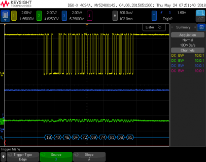
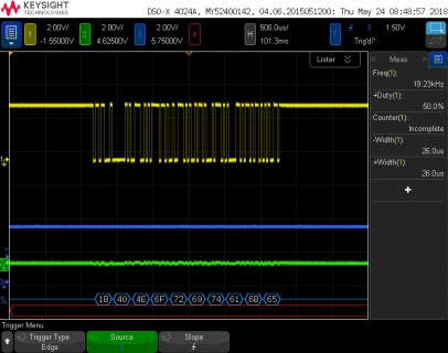
Since I don't have this display, I was only able to verify using my oscilloscope. I tested with the "Hello" example on this line uncommented:

Code:
GE7000_Serial_Async interface(38400,3, 5, 7); // BAUD RATE,SIN,BUSY,RESET

Here's the output running on Arduino Mega.

file.png

Here is the output running on Teensy 3.5 at 120 MHz.

file2.png
 
Hi Paul,

I'll definitely test and give feedback. Frustrating to see things going nowhere. Note that my VFD is the GU-7000 series, not the GE. But I'm going to have a look and write back.
 
I did not buy the display, it was given to me. But it works well for my purpose, and it works great with the Arduino.
 
I tried this new library after renaming the methods for the GU7000 but it didn't work. It looks like the units are different enough to need the proper series code. The result is the same. It's not getting what it wants on the BUSY pin, I think, and it hangs on the WHILE loop, and if I comment that out, it will just write out a random character if I ask it to print "0".

Here's the code from the original GU7000_Serial_Asynch.h

Code:
#ifndef GU7000_SERIAL_ASYNC_H
#define GU7000_SERIAL_ASYNC_H

#include <Noritake_VFD_GU7000.h>
#include <avr/pgmspace.h>

//
// Lookup table
//
typedef struct _DELAY_TABLE
{
  long baud;
  unsigned short rx_delay_centering;
  unsigned short rx_delay_intrabit;
  unsigned short rx_delay_stopbit;
  unsigned short tx_delay;
} DELAY_TABLE;

//
// F_CPU ==  16000000
//
static const DELAY_TABLE PROGMEM table[] = 
{
  //  baud    rxcenter   rxintra    rxstop    tx
  { 115200,   1,         17,        17,       14,    },
  { 38400,    25,        57,        57,       55,    },	
  { 19200,    54,        117,       117,      115,   }, 
  { 9600,     114,       236,       236,      233,   },
};

const int XMIT_START_ADJUSTMENT = 5;

//template <unsigned NORITAKE_VFD_BAUD>
class GU7000_Serial_Async : public GU7000_Interface {

private:
	Noritake_VFD_GU7000 GU7000;
	uint16_t _rx_delay_centering;
	uint16_t _rx_delay_intrabit;
	uint16_t _rx_delay_stopbit;
	uint16_t _tx_delay;
	// private static method for timing
	static inline void tunedDelay(uint16_t delay){ 
	  uint8_t tmp=0;

	  asm volatile("sbiw    %0, 0x01 \n\t"
		"ldi %1, 0xFF \n\t"
		"cpi %A0, 0xFF \n\t"
		"cpc %B0, %1 \n\t"
		"brne .-10 \n\t"
		: "+r" (delay), "+a" (tmp)
		: "0" (delay)
		);
	}
	uint16_t _inverse_logic: 1;
	volatile uint8_t *_receivePortRegister;
	uint8_t _transmitBitMask;
	volatile uint8_t *_transmitPortRegister;
protected:
    unsigned OUT_PIN:4;
    unsigned BUSY_PIN:4;
    unsigned RESET_PIN:4;

	unsigned DEBUG_PIN:8;
    
public:
	
    GU7000_Serial_Async(long baudRate, uint8_t out, uint8_t busy, uint8_t reset):
        OUT_PIN(out), BUSY_PIN(busy), RESET_PIN(reset),
		_rx_delay_centering(0),  _rx_delay_intrabit(0),  _rx_delay_stopbit(0),  _tx_delay(0)
    {
		_rx_delay_centering = _rx_delay_intrabit = _rx_delay_stopbit = _tx_delay = 0;
		
		//Set TX
		_transmitBitMask = digitalPinToBitMask(out);
		uint8_t port = digitalPinToPort(out);
		_transmitPortRegister = portOutputRegister(port);
		
		//Set delay for TX
		for (unsigned i=0; i<sizeof(table)/sizeof(table[0]); ++i)
		{
			long baud = pgm_read_dword(&table[i].baud);
			if (baud == baudRate)
			{
			  _rx_delay_centering = pgm_read_word(&table[i].rx_delay_centering);
			  _rx_delay_intrabit = pgm_read_word(&table[i].rx_delay_intrabit);
			  _rx_delay_stopbit = pgm_read_word(&table[i].rx_delay_stopbit);
			  _tx_delay = pgm_read_word(&table[i].tx_delay);
			  break;
			}
		}
	}
	
    void init() {
        RAISE(RESET);
		DIRECTION(OUT,1);
    	DIRECTION(RESET,1);
    	DIRECTION(BUSY,0);
		//set model class		
		if(getModelClass==7003 || getModelClass==7903 || getModelClass==7053) {
			_inverse_logic = 0;
			RAISE(OUT);
		}else{
			_inverse_logic = 1;
			LOWER(OUT);
		}

				
    }
    void tx_pin_write(uint8_t pin_state){
		if (pin_state == LOW)
			*_transmitPortRegister &= ~_transmitBitMask;
		else
			*_transmitPortRegister |= _transmitBitMask;
	}

    void write(uint8_t data) {
		// Check for busy signal
		
		
		if (!_inverse_logic)
			while (CHECK(BUSY));
		else
			while (!CHECK(BUSY));
		
		uint8_t oldSREG = SREG;
		cli();  // turn off interrupts for a clean txmit

		// Write the start bit
		tx_pin_write(_inverse_logic ? HIGH : LOW);
		tunedDelay(_tx_delay + XMIT_START_ADJUSTMENT);
		
		// Write each of the 8 bits
		if (!_inverse_logic)
		{
			for (byte i = 0x01; i; i <<= 1) {
				
				if (data & i)
    				tx_pin_write(HIGH); // send 0
				else
					tx_pin_write(LOW); // send 1
				tunedDelay(_tx_delay);
    			
    		}
			tx_pin_write(HIGH);
		}
		else
		{
			for (byte i = 0x01; i; i <<= 1) {
				if (data & i)
    				tx_pin_write(LOW); // send 1
				else
					tx_pin_write(HIGH); // send 0
				tunedDelay(_tx_delay);
    		}
			tx_pin_write(LOW);
		}
		SREG = oldSREG; // turn interrupts back on
		tunedDelay(_tx_delay);
	}

   
    void hardReset() {
        init();
    	LOWER(RESET);
    	_delay_ms(1);
    	RAISE(RESET);
    	_delay_ms(100);
		
		if(getModelClass==7003 || getModelClass==7903|| getModelClass==7053)
    		while (CHECK(BUSY));
		else
			while (!CHECK(BUSY));
		
	}
};

#endif
 
One thing that I don't get, is that I can't even get it to do a reset through its own GU7000_reset() method on the Teensy. The only way I can get it to reset is by doing pinMode(35, OUTPUT), which does the reset, then a digitalWrite(35, HIGH) to set it back to normal.
 
Big update, as soon as I posted the previous.

I was playing with the sequence of reset, and delays inside those reset and init functions, trying different things, replacing their RAISE and LOWER methods with actual digitalWrite and pinMode, and all of a sudden, the proper data briefly flashed on the display instead of garbage (but went away). This really has something to do with timing and delay. Of course, I'm still using your latest library, which is not the correct one for my display. But this is an improvement, even though I'm going around blindly.
 
Here's what I modified that got the data to briefly flash on the screen before disappearing, instead of garbage.

Code:
void init(){
        //RAISE(RESET);
		//digitalWrite(35, HIGH);
		//DIRECTION(OUT,1);
		pinMode(33, OUTPUT);
    	//DIRECTION(RESET,1);
		pinMode(35, OUTPUT);
    	//DIRECTION(BUSY,0);
		pinMode(34, INPUT);
		//set model class		
		if(getModelClass==7003 || getModelClass==7903 || getModelClass==7053 || getModelClass==7933) {
			_inverse_logic = 0;
			RAISE(OUT);
		}else{
			_inverse_logic = 1;
			LOWER(OUT);
		}
    }

Code:
void hardReset() {
        init();		
		//_delay_ms(10);
    	//LOWER(RESET);		
    	//digitalWrite(35, LOW);
		_delay_ms(1);
    	//RAISE(RESET);
    	digitalWrite(35, HIGH);
		_delay_ms(100);
			
		//Added model numbers for OLED modules
		/*
		if(getModelClass==7003 || getModelClass==7903 || getModelClass==7053 || getModelClass==7032 || getModelClass==7933)
    		while (CHECK(BUSY));
		else
			while (!CHECK(BUSY));
		Serial.print("state:");Serial.print(CHECK(BUSY));
		*/
	}

I don't completely understand it, but it made things better. The rest is unchanged from your modified library, except that I'm still disabling the BUSY signal check.
 
What makes no sense to me so far, is if you look at the init() function, if I uncomment the DIRECTION(OUT, 1) line and comment out my pinMode(33, OUTPUT) line, the improvement goes away, even though they are supposed to do exactly the same thing (DIRECTION is defined inside GU7000_interface.h). It's almost as if it doesn't know the right ports.

They are defined this way (which works on the Arduino):
Code:
GU7000_Serial_Async interface1(19200, 33, 34, 35); // BAUD RATE,SIN,BUSY,RESET
Noritake_VFD_GU7000 vfd1;

And in setup():

Code:
vfd1.begin(140, 32);       // 140x32 module
vfd1.interface(interface1); // select which interface to use
vfd1.GU7000_reset();       // reset module

vfd1.print("0");

Although it does know the right ports because at some point, I tried to change INPUT to INPUT_PULLUP in the DIRECTION method to see what it would do to the BUSY port, and it made it flip from 0 to 1.

Perhaps it's just a matter of speed and the difference between calling digitalWrite through the function vs directly.
 
Last edited:
Another update: it doesn't actually flash, or disappear, as I was explaining. I was also output some large graphics, and with this library, they don't seem to fit on the screen as they should, so until there's a fix for that (for the GU-7000 library), just outputting small things like a couple characters actually works.
 
It works!!!

Well, almost. It turns out that the screen blanks out as soon as the 2 big speedo numbers appear in the middle, between the arrows. I'm not sure yet but I believe this might be voltage. I think there's a voltage drop on the breadboard and the display is not getting enough to display all those dots, but I'm going to test this more as I can.

View attachment 13889

Edit: yep, if I lower the screen brightness to 25%, all of the graphics appear, so this has to be just a voltage issue. Note that I still have to disable the BUSY signal check in both the reset and write functions, or it will hang, as it always seems to be 0. The Noritake spec says the SBUSY output is 4.0V on high and 0V on low, if that is relevant.
 
On Teensy I/O pins start in a neutral/disabled state and different in some ways to AVR Arduinos.

On Teensy the first Write won't work without the pinMode() before it::
Code:
void init(){
		pinMode(35, OUTPUT);
		digitalWrite(35, HIGH);
    // ...
}
 
Ah, yes, that makes sense. I edited the init function to have their DIRECTION first then RAISE on the reset pin, and it seems to work, so I'll redo this to be clean. Thanks all for the help, especially you taking the time to rework that file, Paul, looks like that asm function for the delay is the most important thing to get right. As of now, it seems that things are working just fine with the GE library on the GU unit. Except for the SBUSY, but it looks like it's working without it though. I'm able to update the display relatively fast (those big numbers are not quick to redraw, and I've coded my function to only redraw the one that needs it), but the real life test will tell me if there's any lag.
 
One oddity though. In init(), if I have this, it won't work:

Code:
DIRECTION(OUT,1);
//pinMode(33, OUTPUT);

If I have this, it works:

Code:
//DIRECTION(OUT,1);
pinMode(33, OUTPUT);

DIRECTION being defined this way:

Code:
#define DIRECTION(X,D)	if (D) pinMode(X##_PIN, OUTPUT); else pinMode(X##_PIN, INPUT)
 
Status
Not open for further replies.
Back
Top