ESP8266 Add-On for Teensy 3.2

Status
Not open for further replies.
Serial3 still hits AudioBoard pin 7.
<edit> that alt MOSI pin is also used for the FLASH chip SPI as well as the SD right MM?

Since I don't need the Audio board - I think going the optimal route to test the ESP concept as planned makes sense. Looking at Frank's TOWER - those using it are inclined to be able to work around issues and already have a less than 'appallingly small' setup. Audio Board users could end mount the board as shown and not connect p9&p10 hand wire to Rx1/Tx1 and CTS as needed?
 
Last edited:
According to http://www.pjrc.com/teensy/td_uart.html, only Serial1 has hardware CTS/RTS, but in the future Serial2/Serial3 could support it as well. RTS/CTS pin assignment are:

  • Serial1: RTS: 6 or 19; CTS: 18 or 20.
  • Serial2 (future): RTS: 22; CTS 23.
  • Serial3 (future): RTS: 2; CTS 14.

<edit>
The standard MOSI pin (11) overlaps with I2S's MCLK and the SCLK pin (13) overlaps with I2S's RX. If you use the SD card on the Audio board, you would need to access the MOSI/SCLK functions using the alternate pins.

Of course, the current UART2, 3 "could" implement CTS in software by using a "software CTS" GPIO pin as a pin-change interrupt with an ISR that tells the main UART ISR to pause sending when the current one or two bytes are finished. Two, as there is one register behind the UART shift-out register, so worst case, two bytes are sent after CTS goes false. With hardware CTS, I'd expect no more than one after CTS goes false.
 
the current UART2, 3 "could" implement CTS in software by using a "software CTS" GPIO pin as a pin-change interrupt with an ISR that tells the main UART ISR to pause sending when the current one or two bytes are finished.

A lot of things "could" happen if there were far more hours in every day!

Since hardware CTS works well, odds are pretty much zero anyone will ever go to the considerable trouble to implement and debug this.
 
Since hardware CTS works well, odds are pretty much zero anyone will ever go to the considerable trouble to implement and debug this.
Perhaps I misunderstood.. Software CTS would apply on the LC as there is hardware CTS only of the first UART, right?
 
Actually, Teensy LC doesn't support CTS at all, on any of its serial ports.

Just to be perfectly clear, "software CTS would apply" should not be misunderstood by imply CTS is implement by in software. It isn't, and probably never will be implemented on Teensy LC.

This would only apply in some theoretical alternate reality where I could invest huge amounts of software work on every minor feature, or where merely wishing for a feature would magically cause well tested source code to pop into existance! In the practical real world, software-based CTS is a feature I'm not planning to ever implement.

If you need full RTS/CTS hardware flow control, use Teensy 3.2.

I want to be absolutely clear on this point. Often people search for info and find these old threads with conversation about possibly developing a feature, which never happened. Wishful thinking and wanting can be a powerful force. The last thing I want is for people to mistakenly believe the low-end Teensy LC is capable of features PJRC doesn't support. There's a huge difference between things that could theoretically be supported if someone put a lot of work into writing the software, and features an actually selling product really does support.
 
.... probably never will be implemented on Teensy LC.

This would only apply in some theoretical alternate reality where I could invest huge amounts of software work
No mention of appeal to PJRC to implement software CTS. Just saying if someone must have software CTS, "someone" could implement it (e.g., the person needing it) !
A teensy bit of overreaction?
 
A teensy bit of overreaction?

Conversations like this have a way of turning into unrealistic expectations when people who *really* want a particular feature find it after lots of searching.

You may see the context of this conversation as perfectly clear. But believe me, when you sell a dev board/platform for any good length of time, you see all sorts of unpleasant misunderstands happen over language such as used in this thread.

I always strive to be clear and set realistic expectations for what Teensy can really do.
 
I've posted the latest ESP8266 Teensy add-on for sale at Tindie and Tim (defragster) has been putting it through its paces. Still don't have the OTA Teensy programming functional and probably need some help with this...
 
Going to the RAW ESP8266 units was something I was looking to avoid but the onehorse solution with a custom 'fit' to T_3.2. I ended up seeing best results from the Arduino IDE programming - (after I got breadboard power right). So still ramping up between raw ESP_12E's and the first 'Serial3' unit from onehorse - with a Serial1 (for T_3.1) and a Serial2 unit in my mailbox now.

Gotten the Arduino OTA work to ESP8266 and hoping to post a GitHub sample that does something stable. Seeing that SPIFFS on ESP are SPI Flash File System that swap code EPROM for file system. I think that may be the easy key to having an ESP pull a HEX file - store it and then present it to the "TBD OTA Teensy Loader". I worked with FrankB on his from SD card and it worked well.

Question for Paul @ PJRC is - what preconditions do you see as necessary/stable before starting. i.e. confirm mode of transport (Serial ?) from ESP flash, and extent of 'user' code support in both the ESP and the T_3.2 (saying 3.2 for now as it has the power to secure an ESP8266) - on the code front - how much of this will be able to be localized in the 'programming chip'. Frank was working with HALF of flash - only because he needed code in RAM to allow writing the full flash. Certainly this is not expected to be highest PJRC priority with other things brewing - but could get some ground work done perhaps. This would work with any ESP unit with enough flash to set aside the SPIFFS area needed without any added hardware.

Onehorse has a 1MB Flash so a 756/256 split would allow >350KB ESP code to OTA upload ( 250KB is MIN sketch with WiFi stack ) and the 256 SPIFFS area could hold nearly a full T_3.2 of code. I need to split my flash and get this working - it isn't clear the SPIFFS splitting is currently robust from Arduino. So lots of little issues for a new environment, made painful by the IDE forcing a full recompile when TOOLS changing the object device. That and I just got my third hardware iteration wired over the weekend - with 2 more in the mail.
 
Last edited:
Taking this stevech quote from another thread to suggest that Serial will indeed be the way to feed data to the 'programmer processor'?:

But Teensy 3 uses a special protocol via USB. This same scheme could be done with Teensy, by using a hardware serial port on each Teensy board. There is a small microprocessor on the Teensy 3 runs a reset/power-on and copies bootloader code to the main ARM CPU and causes that to run.
 
I just gave GitHub my ESP sample sketch with 8266 OTA update capability and a handy web page set for auto refresh from browser.

Some usage details and links for starting in the ReadMe

Web pages work well - tested the OTA update to load/reload the same sketch 3+ times (with output edits) only on the onehorse unit. have to swap the serial programmer one last time to get it on the 12E . . .

https://github.com/Defragster/ArduinoTeensyESP8266
 
Last edited:
BOTH ESP units (stock 12E and onehorse Serial3 ) running the OTA upload code and being stable! And both routing their serial I/O to dedicated Teensy that routes out to USB. OTA upload to ESP is at least 3 times faster it seems than Serial@115200baud.

The 12E going to Serial2 - as noted I started with the Serial3 from onehorse and for fun I wired the Rx/Tx to alternate Serial2 pins 26 and 31. This lets me use the wires direct for now as needed to do Serial upload - until I get the Teensy proxy code as used by FrankB tested.
 
SPIFFS running on both ESP's - with OTA FS Image dump! Note: the first linked wired SPIFFS upload never completed but the OTA version does

[SPIFFS] data : C:\tCode\ESP\SPIFFS_ppS3_jan20a\data
[SPIFFS] size : 256
[SPIFFS] page : 256
[SPIFFS] block : 4096
/FB_Proxy_AltS2.TEENSY31.hex

/here.txt

[SPIFFS] upload : C:\Users\Tim\AppData\Local\Temp\builda641ff5aa2ace8b7259ea77ef915daca.spiffs/SPIFFS_ppS3_jan20a.spiffs.bin
[SPIFFS] IP : 192.168.1.108

Support for OTA upload, works only with the default port and no password <this means it works>
Followed directions from original SPIFFS link - but downloaded the OTA JAR 0.2.0 and it works as suggested. It functions with the same 'BasicOTA' sketch functionality I have on GitHub HelloServer example - updated with SPIFFS demo

Below I do a DIR of the FS and open a file common to both ESP's with unique text identifying the unit. Note the one file is a Teensy.HEX file I OTA loaded - in theory I could open this file and pipe it over serial to FrankB's 'Outlaw_Upload' code and have a working OTA Teensy Uploader. Since a '.hex' file is just plain text it should work the same.

NOTE: The FS image comes from above indicated sketch dir '\data' - but as you can see below it appears on the root. It seems OTA dumps of FS would flash a full '.bin' of that '\data' directory overwriting the current contents.

@Paul - when ready - with this grunt work done you'd have enough to start to define and and test Teensy OTA upload from ESP FS Storage - the "end user" ESP code would just need to implement a way to store then upload a given hex file. I'm sure onehorse or myself could even get you a working ESP unit with this needed setup done ( and pre-loaded with a couple blink sketches ) and ready for you to minimize your startup time. The ESP hex 'server' code is all in an Arduino Sketch. The Teensy can control the ESP with EN/PGM pins as needed to reboot it - and for your work - could take USB commands to tell the ESP unit what to do over incoming serial.

SPIFFS TRUE
file here.txt found!
pp32
This is the Onehorse Serial 3 ESP Unit.
-------
DIR /
/FB_Proxy_AltS2.TEENSY31.hex Len=46683
/here.txt Len=45

SPIFFS TRUE
file here.txt found!
_12E
This is the stock ESP-12E Serial2 Unit.

-------
DIR /
/FB_Proxy_AltS2.TEENSY31.hex Len=46683
/here.txt Len=47
 
Last edited:
I'll start a thread for my efforts and GitHub work once it might be clean enough to use - short update.

Working with a Kris on these to good effect. More time on connecting hardware as I got three sample units on Serial 1 & 2 & 3. Some updates to GitHub, but not pretty yet. Generally reliable and good for running day(s) of updates of a simple page at 2.5 second updates without problems - even 3 units at a time in separate browser pages.

I implemented an ESTOP pin the Teensy can set to have the ESP recognize in setup() to if (ESTOP) {any risky user/new code} that may cause faults - which prevents the OTA code from running - requiring serial attachment to restore. With that the OTA code is quite robust - and OTA updates are at least 3 if not 6 times faster.

I've tested the Serial3 hardware wired to Serial2-Alternate-pins-26-and-31 and that works - so if conflicting topside pins are an issue the Serial# pins can easily be reconfigured to Alternate pins.

Someday I'll try another IDE - until then I'm using the 1.6.7 IDE. It makes jumping back to ESP scary and at least two clicks - scary if you don't see other needed settings got returned to default trashing OTA usage. For now it was easier to set up the IDE on a spare networked computer and remote desktop to it for the OTA uploads. Very cool! I told that remote IDE I was using external editor - I edit the networked code save and then in remote window just to UPLOAD and watch for compile for errors and upload. The Device beside me will keep running while the OTA update begins making it spew out a set of % complete debug spew - then it typically restarts and comes up running, sometime I need to have Teensy Reset it.

For other tasks that used to take buttons or jumper wires - I put a command processor in the Teensy. So I can use TYQT to RESET/PGM or whatever seems like worthy process. I can even manually drop baud rate to watch boot messages.
 
defragster

Ha! This is what I was looking for. I had pegged on a separate thread and found your link to this one. I'm fighting IRremote right now but I will come back to this once I'm done.

For what's worth, I've been working on a same scenario for a completely different board (a flight controller based on a MIPS Cortex-M4F). The code running on the ESP8266 is a bridge between UDP and UART (using a specific protocol) running at 921600 bps. OTA to the ESP itself is working but I have yet to get OTA firmware upgrades to the flight controller. If you're curious, you can find my own progress here.

Thanks!
 
@grubba - cool - I see you are not using Arduino IDE for ESP8266 programming. Not sure if that impacts your efforts and joy in using mine?

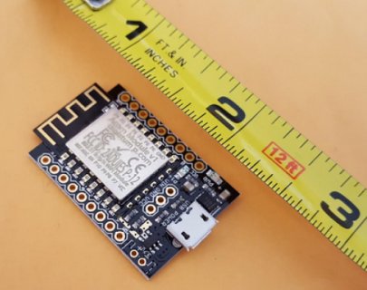
My first connect ESP-12E hardware was underpowered on my breadboard and failed running everything I tried - then after settling on Arduino I finally saw and fixed the power and it worked perfectly without learning a new environment so I'm staying with Arduino for now to program the ESP's. I had been avoiding doing direct ESP interface waiting for Kickstarter OAK that will use Particle.io - but after (6+) months waiting I decided to work with onehorse and his direct Teensy mount ESP units on this thread - only covers 6 pins of the 14 in length and direct connects to (T_3.2 power) and connecting chosen 8 pins for essential Rx/Tx and some I/O with 5 more free end pins exposed and on the newer models a 2-3" wire antenna keeps it in free air without adding any 'hard antenna' size to worry about covering with other PCB's. And when onehorse can get 4MB flash that will make a better version on his same 0.6" x 0.7" footprint.
 
... I had been avoiding doing direct ESP interface waiting for Kickstarter OAK that will use Particle.io -.
The Digistump OAK boards I ordered arrived today (So. Calif.). Low cost.
They are using the IDE/backend that Particle.io uses. The OAK board is much smaller and pin-limited than the Adafruit board I got a few weeks ago. I have some other ESP8266 boards and one with the Broadcom ARM/WiFi solution.

2016-02-08_125915.jpgView attachment 2016-02-08_125712.pdf

Wire antenna should be 1/4 wavelength at 2.4GHz (times about 0.7)
 
Last edited:
Wire antenna should be 1/4 wavelength at 2.4GHz (times about 0.7)

@stevech - in English ( or metric :) ) - how big should the wire antenna be for this radio?

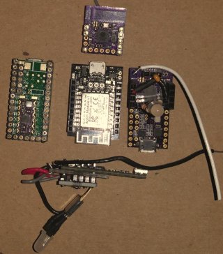
Here is an OAK ( In the middle - I got my BETA unit weeks ago - the rest of my order to be delivered in a couple weeks after the Chinese lunar new year ). Surrounded by three onehorse units and Teensy's.

A bare T_3.1 with it's Serial1 unit taking 5V on top - on right the Serial2 unit (T_3.2 top mounted) with wire antenna. On bottom a Serial3 unit ported to Serial2 Alternate pins T_3.2 bottom mounted under FrankB's ConnectorBoard to bring out the bottom pads. (Red&Gray wires can now be clipped and soldered as serial programming through Teensy works when OTA fails - they bring the Alt Serial2 pins over - Black wires are GND from when I needed to short for PGM and RESET - The Teensy does that now with USB commands.) I made up socketed RGB LED with resistors - they use an external GND wire. Also each has a 104 cap to stabilize RESET pin for an issue I found on one time Teensy connecting to the pin causing baud rate to drop to save a software workaround - onehorse updating his design..

I got the OAK to do an initial OTA update and got a sketch to load - it was more work than it was getting Arduino to work directly on these ESP's (per my GitHub) - OAK was BETA and it will get better - but the size and fit getting twin CPU's where one if WiFi capable and the other a Teensy is a promising combo. Especially 0.4" high and 0.7" wide and 1.4" long.

Serial123_OAK.jpg

<edit> I found this searching - is it right?
A full wavelength of 2.4GHZ is 12.5 cm.
A 1/2 wavelength is 6.25 cm
 
Last edited:
yes on wavelength.
I haven't looked on the Oak PCB to determine how you disconnect the PCB antenna. You wouldn't want both connected.
PCB antenna probably has about -3dBi of loss (negative gain). Wire antenna would be about +2dBi of gain. And the wire antenna can be bent to be vertical.
 
Thanks stevech - so 3.125 cm for 1/4 wavelength - looks like I was aimed more toward 1/2 wavelength at 2.5". My end use won't have fixed directional antenna location - but will be within 100 feet. Does that indicate one wave portion over another?

Good luck modifying the OAK antenna. That uses the improved 12F PCB antenna which was some 30% improved IIRC over the 12E I read in passing.

<edit> Note the Serial2 unit from onehorse ships with a solder pad for the antenna wire - which according to stevech should be about 2.1875 cm with the 0.70 multiplier reduction.
 
Last edited:
1/4 wavelength x 0.7 length antenna is intended to get the impedance near that expected by the RF circuitry. The result is more radiated power, less lost to impedance mismatch a.k.a. Voltage Standing Wave Ratio (VSWR). A bad VSWR will waste power that is reflected back to the transmitter circuit, and vice-versa for received signals. Nothing here is very precise due to these minimal-RF radios, lack of a bandpass filter between antenna and radio, etc.

1/4 wavelength gets close to the usual 50 ohm antenna impedance expected by most radios.

Some boards have a jumper-cut to enable a solder pad or a U.FL connector for a better antenna. The latter is what you want, but el cheapo radios leave that $0.25 connector out.

Don't tack a wire onto the existing PCB antenna - -probably worse than not. But if you do, try it at the radio end of the PCB trace. Maybe cut the trace to abandon the PCB antenna.

100-300 ft is doable if line of sight with WiFi, and semi-decent antennas and the usual 30-100mW WiFi transmitter power. Higher data rates (modulation order in WiFi) = lower power, with today's OFDM WiFi. So best range is had by forcing the radio to use low rates.This is OK for typical telemetry.

The sub-1GHz radios are more commonly used for telemetry due to the lower frequency (meaning longer range), less attenuation when passing through non-masonry walls/floors, etc.

Best way to get more gain is to put a good gain antenna on the access device end of the link - WiFi router or WiFi Access Point (AP). Like a 9-12dBi gain omni, or a directional patch (square), or a yagi.

Percent (%) in RF signal strength is not very meaningful as it's just relative to some unknown. Received signal strength is measured in absolute terms, as dBm (decibels relative to 1 milliwatt) of received power. 0dBm is 1mW. So 10dbM is 10mW. 20dBm is 100mW, etc. Typical WiFi received signal strength for a middle-range bit rate is about -70dBm, which is 70dB down from 0dBm. As distance doubles, the received signal decreases by about 3dB. As frequency doubles (e.g., from the 900MHz band to the 1.8GHz band), there is about 6dB of increased path loss.

So RF Link Budget engineering is a tradeoff of: Receiver bandwidth (WiFi is most often 20MHz per IEEE; but sub-1GHz telemetry is typically 0.1MHz. That's why the range is so much better, though the net bit rate is typically 10Kbps to 100Kbps. Trading range for speed. Laws of physics!
 
Last edited:
IIRC this board has a solder pad at the top left corner of the board. I would connect the antenna (1.25-inch stranded, insulated copper wire) there. In later designs I have replaced the solder pad with a through-hole, which is more robust. Be careful not to move the soldered antenna around too much since you could dislodge the solder pad.
 
Status
Not open for further replies.
Back
Top