ESP8266 Add-On for Teensy 3.2

Status
Not open for further replies.

onehorse

Well-known member
I redesigned the ESP8266 add-on I've been playing with to work with the Teensy 3.2.

I was able to dispense with the on-board 3V3 LDO and use the Teensy 3.2's 500 mA regulator instead. I also reduced the boards size and designed it to mount on the more-natural non-USB end of the Teensy. I broke out the Teensy program pin connected to ESP8266 pin 5. The user needs to choose whether to connect pin 5 or the program pin to the Teensy. The (Paul's) idea of breaking out the program pin is to allow OTA programming of the Teensy from the ESP8266 via Serial3 transfer to the Teensy. I haven't demonstrated this yet but with this board all of the pieces are in place to do so.

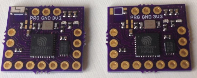
Here is what the board looks like:
ESP8266_T3.2.jpg


I have been experimenting with different antennas. I've found just adding a solder point and attaching a few-cm-long wire gives the best reception. This is also the cheapest solution and allows the smallest form factor. I'll make one more revision with this antenna type and put these boards up for sale at Tindie.
ESP8266_Teensy3.2_back.jpg

I hope onoe of the bright bulbs on this forum can demonstrate the OTA functionality with this board.
 
Last edited:
That is pretty amazing, one-horse!

Look forward to seeing that puppy gestate and get released to the general public. Applying for an FCC license? ;)
 
Looks like a great step forward - Less PCB area - better placement [on Teensy and exposable Antenna run !] - Fewer parts and expense! Hits Serial2 pins?

FrankB showed me WORKING (half codespace) OTA [SD flash] coding - And Paul posted months back he was waiting for a trusted ESP8266 type solution for his OTA attempt/follow-through. This could be the ticket for any needed Bootloader hook from PJRC to make it right at full codespace - will just need spare flash data to hold 256KB for T_3.2 or more for the T_3x++
 
I am using an 8 Mbit, 1 Mbyte SPI flash chip so there should be plenty of space. The UART is designed to connect to Serial3 pins 7 and 8.

I need someone to load the latest firmware since I have only succeeded in getting the V.20 firmware HWGuy linked me to work. And AT commands only at that. I am way behind the curve in use of the ESP8266 even though I have finally got a handle on how to design hardware with it.

Presumably the latest firmware allows ESP8266 OTA programming, etc.

I ordered twelve boards, which should be on Tindie in a week or so.
 
Serial3 ? That means less fifo.... Does serial3 support cts ?
Does it work when placed under the teensy, too (RF, antenna) ?

Edit: ...not compatible with the audioboard, right ? Is SPI available ?
 
Last edited:
Frank hit my nail on the head - no FIFO on Serial3 - even with flow control the serial will be slower/more cpu intensive? Hoping antenna wire can route 'as needed' to free air?

Here are those posts looking for good ESP8266 to support:
@onehorse - what happened to your plans for a esp8266 board? Were you going to make one in Teensy form factor, or was that just wishful thinking on my part?
I ask because I'm planning to work on esp8266-based OTA programming in Teensy 3.2's bootloader, after the upcoming peripheral board is released.
 
It should work fine when mounted under the Teensy 3.2 You will have to solder on a wire which can be wrapped around the Teensy to make a still-small package. I specifically left open the SPI port (pins 11-13) and you don't have to connect all of the pins of the ESP8266 board anyway. You really only need RX3/TX3, 3V3/GND and I would think maybe EN (pin 16) to turn it on and off from the Teensy as well as PROG for OTA. The UART could be rerouted to use RX2/TX2. I chose RX3/TX3 for layout convenience. if there is a serious limitation that switching to RX2/TX2 would correct I would consider redesigning.
 
https://github.com/PaulStoffregen/cores/blob/master/teensy3/serial2.c#L83
// UART0 and UART1 are clocked by F_CPU, UART2 is clocked by F_BUS
// UART0 has 8 byte fifo, UART1 and UART2 have 1 byte buffer

109 #ifdef HAS_KINETISK_UART1_FIFO
110 UART1_C1 = UART_C1_ILT;
111 UART1_TWFIFO = 2; // tx watermark, causes S1_TDRE to set
112 UART1_RWFIFO = 4; // rx watermark, causes S1_RDRF to set
113 UART1_PFIFO = UART_PFIFO_TXFE | UART_PFIFO_RXFE;
114 #else
115 UART1_C1 = 0;
116 UART1_PFIFO = 0;
117 #endif

Though that code comment may be in generic to the T_3?

Serial2 on UART1 can run 4-6 Mbps.

http://www.pjrc.com/teensy/teensy31.html#specs
 
Is Serial3 using UART2?

Yes. Serial1 uses UART0, Serial2 uses UART1, Serial3 uses UART2.

Only UART0 and UART1 have the FIFOs for more efficient transfer at fast baud rates. To really work well at those speeds, RTS & CTS are probably also necessary. CTS is limited to specific pins by hardware. RTS can be any digital pin (we don't use the hardware to generate RTS).
 
Only UART0 and UART1 have the FIFOs for more efficient transfer at fast baud rates.

Isn't it true that none of the LC's UARTs have a FIFO?

I'd think that at 115200, a FIFO-less UART, with the CORRECTLY DESIGNED driver/ISR and collaborating app, would work OK. I've done so many times.
 
Last edited:
Pins 13 and 15 are ESP8266 CTR and RTS and it looks like the ESP8266 can support full flow control for its UART port.

Which specific Teensy 3.2 pins are hardware CTS? And does it make sense to redesign the ESP8266 add-on to use Serial2 instead of Serial3? Should I redesign it so that ESP8266 CTS aligns with Teensy 3.2 CTS? I don't really understand the rate limits well enough to make these design choices without some help.

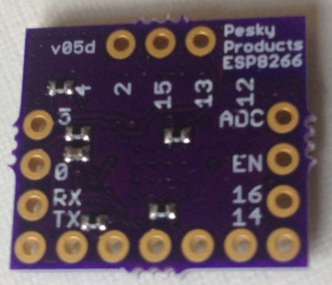
Right now ESP8266 pins 13 and 15 are on the back of the add-on and two wires could be soldered onto these pin holes to connect to the Teensy 3.2 CTS/RTS for testing. Maybe it would make sense for someone to test the difference in performance between using the ESP8266 with Teensy Serial3 vs. Teensy Serial2 vs. Teensy Serial2 with flow control. The current design should allow this.
 
stevech: no FIFO's on the LC - my testing showed it failing somewhere over 200Kbps. With two active T_3.1/3.2 units going in/out EACH of Serial1&2 to each other I was seeing usable I/O transfer at 4-6Mbps - I didn't test it to always be perfect - but it seems like it was for days at a time with 'buffer sized' ping messages.

DUFF made this thread: Teensy-Hardware-Flow-Control-RTS-CTS

onehorse: There are a couple solutions for flow control in software on the Teensy. Frank did one just raising a pin to say not CTS in some fashion (currently on Serial1 only) and there is another more complete library from DUFF as I recall. The solutions are software controlled so hand wiring pins seems perfectly fine.

One other ESP8266 user '???' got this mossy rock rolling when dumping large web page/data blobs was found to hang his ESP8266 unit, but that it ran so much faster at 4Mbps. He set up flow control and got stability as I recall.
 
Last edited:
Hm,

what would you like to test ?

For RTS/CTS you'd have to test your app...
It's a flow control. If your app is fast enough, you may not need it. But if you app can't handle high transfer rates, you need a flow control.
Testing this handshake with other apps make no sense.It's not a matter of "teensy or SerialX" can handle it.
The Teensy could be 100 0times faster and still need handshake.
On the other hand, you could slow down the transfer down to 300 BIT/s and still need hardware-handshake.
It depends on the software and what you like to do.

For example, one of my prjects connects to a audiostream-server on the internet. The transfer is not very fast (128KBit/s) , but due to different reasons i configure the Serial1 to 2..3 MBit/s. I sTill need rts/cts, because i have long time in between, where the software is busy with other tasks, so it can't read the buffer - it would overflow without handshake.

I guess, that Paul needs this handshake for OTA Programming too. Maybe.

Edit_
If you want to test if a fifo is needed: Of Course, there is no strong need for a fifo. It works without, too. But..think..why do you think did freescale (and dozens of other hardware-designers) implement this fifo ? :) It makes things more usable. The fifo reduces the Interrupt-rate and increases the performance of the rest of the system.

Such tests make no sense.

Edit_
Why did you choose to not support the Audioboard ? What's the benefit ?
 
Last edited:
no experience using flow control ....

The most common mistake involves connecting 2 outputs and 2 inputs to each other.

Just like the TX output from one device needs to connect to the RX input of the other, the RTS output needs to connect to the CTS input. If you connect same-named signals together, like you'd do with I2C or SPI, it won't work.

However, it's a common practice with DB9 connectors having RS-232 signal levels to mis-label all the pins on the non-PC device (female connector). The TX pin is actually labeled RX, and so on, so same-name pins line up (or you can consider this as both sides label the pins with the PC's functionality). This is generally only done with DB9 connectors. On microcontrollers and breakout boards with TTL or 3V CMOS logic levels, the pins are almost always labeled correctly. The assumption is you'll know to connect TX to RX and RTS to CTS.

It's a good idea to put a pulldown resistor at the CTS input, so the device will still transmit if CTS is left unconnected.
 
I designed these boards so that ESP8266 RX aligns with Teensy TX, and vice versa. I checked that they work when mounted on the Teensy as intended for Serial 1 and Serial 3. Presumably the same will go for Serial 2.

The ESP8266 board has a pull down resistor on RTS (GPIO15), which is the Teensy CTS input. So to use flow control on Serial2, one would have to solder a wire from GPIO15 on the ESP8266 board to Teensy 3.2 pin 23. And also solder a wire from ESP8266 GPIO13 (ESP8266 CTS) to any other Teensy 3.2 digital IO pin for Teensy RTS. ESP8266 GPIO 13 & 15 are located next to each other on the "back" edge of the ESP8266 board "facing" the Teensy USB connector so this would be easy and relatively convenient to do even with short jumper wires.
 
Last edited:
Why did you choose to not support the Audioboard ? What's the benefit ?

Well, although I have an Audio board I almost never use it and it is not my first (or second) priority for support. So I just made sure to keep the SPI port free and minimized the size and maximized the utility of the ESP8266 add-on.

But why do you say it won't support the Audio board? Does 3V3, GND, RX2/TX2 interfere? Maybe RX3/TX3 wouldn't? What is incompatible?

Remember, you don't have to connect every pin of the ESP8266 board to the Teensy...
 
Unfortunately, the Audio card uses pin 7 for alternate MOSI, pin 9 for BCLK (i2S), and pin 10 for SDCS (SD select). This means Serial3 is unavailable due to pin 7, and Serial2 is unavailable using the default pins due to pins 9-10.

The only serial UARTs that are available are:
  • Serial1 (pins 0/1)
  • Serial1 using alternate pins (5, 21)
  • Serial2 using alternate pins (26, 31 on pads underneath the Teensy)

I put together this spreadsheet to show the pin usages with the Audio board: https://docs.google.com/spreadsheet...4ZridMGn-Yw2zyfYeeePysx2DKE/edit#gid=89568765.

Pins 0-5, 9, 16-17, and 20-21 are not used by the Audio board. Pins 18-19 can be used for i2c usage. Pin 6 is available if you don't solder the flash memory card to the board.
 
For the pins this board ideally needs it seems onehorse hit the sweetspot for 3.3V/Gnd/PGM and Rx2/Tx2 - just needs a wire for p23_CTS. Suits my need as shown losing the audio board okay.

For Serial2, pin 23 is the only option for CTS.
For Serial1 - what pin(s) are CTS capable?
Moving it up to pick up ALT_Rx1/Tx1 (5&21) would lose PGM and GND as direct PIN connect.

What interface & pin set is good for OTA PGM attachment to ESP8266? Won't be on USB - but needs to be something that is usable/reliable during OTA programming? Is that any serial#, I2c?
 
So it looks like Serial 3 could still work if one didn't have to use alternate MOSI. There are tradeoffs to everything. It looks like I might need to plan to make both an RX3/TX3 and RX2/TX2 version available.

Is alternate MOSI absolutely essential to make any use of the Audio board or is the assumption that the predominant use for the ESP8266 will be in conjunction with the Audio board and therefore every possible Audio board configuration must be supported by any proposed connectivity solution?

I want to use the ESP8266 connectivity to send sensor data to the web and laptop. Surely there are other applications too that don't require every functionality of the Audio board???
 
According to http://www.pjrc.com/teensy/td_uart.html, only Serial1 has hardware CTS/RTS, but in the future Serial2/Serial3 could support it as well. RTS/CTS pin assignment are:

  • Serial1: RTS: 6 or 19; CTS: 18 or 20.
  • Serial2 (future): RTS: 22; CTS 23.
  • Serial3 (future): RTS: 2; CTS 14.

<edit>
The standard MOSI pin (11) overlaps with I2S's MCLK and the SCLK pin (13) overlaps with I2S's RX. If you use the SD card on the Audio board, you would need to access the MOSI/SCLK functions using the alternate pins.
 
Last edited:
Status
Not open for further replies.
Back
Top