I am making a board with all the teensy chips/components built in by following the schematics and very helpful info from Phillip Schuster.
I am just a bit confused about how to connect the USB lines.
Based on Phillip's guide it looks like the USB data traces must be routed very carefully in order to get the impedance to be about 90ohms?
Phillip used a calculator
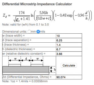 with data for an OSHPark 4-layer board.
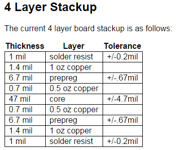
However I am making a 2-layer board
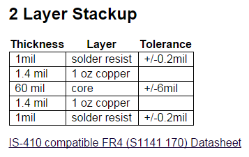
Since the 2-layer has no "prepreg" layer does this mean that I need to use 60mil for the dielectric thickness value for the calculator?
If I use 60mil for the dielectric thickness and 4.5 for the dielectric constant (from the datasheet on OSHpark's site) then messing around with the calculator to get 90ohms gets me:
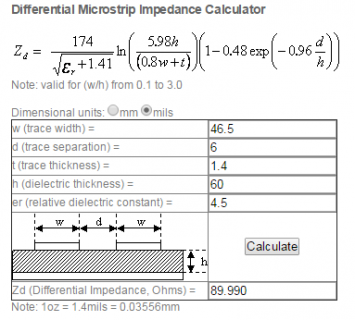
But a trace width of 46.5mils seems huge and ridiculous...
Then I also found this on stack exchange where some guy seems to say that basically for USB low or full speed(12mbps, which I believe the teensy uses?) that none of this really matters and routing the traces well only really matters for higher speeds like 480mbps or higher...
Does anyone know how much routing of the usb data lines really matters for the teensy? Or is this a case of everyone following best practices and never having any problems and so no one really knows if bad routing causes any problems? Has anyone made a custom teensy board with usb traces that didn't quite follow these rules and had any problems?
Here are the actual USB data traces on my board:
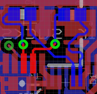
The red traces are from the usb micro connector on one side of the board and the blue are going to the MK20 chip on the other side of the board. There are two 33ohm resistors at the top. I made this before I knew about the rules for routing USB traces and so I am aware that they are pretty terrible... I tried to make the traces the same length which is why they wiggle around a bit.
Thanks for any help or info you have!
I am just a bit confused about how to connect the USB lines.
Based on Phillip's guide it looks like the USB data traces must be routed very carefully in order to get the impedance to be about 90ohms?
Phillip used a calculator
 with data for an OSHPark 4-layer board.
However I am making a 2-layer board

Since the 2-layer has no "prepreg" layer does this mean that I need to use 60mil for the dielectric thickness value for the calculator?
If I use 60mil for the dielectric thickness and 4.5 for the dielectric constant (from the datasheet on OSHpark's site) then messing around with the calculator to get 90ohms gets me:

But a trace width of 46.5mils seems huge and ridiculous...
Then I also found this on stack exchange where some guy seems to say that basically for USB low or full speed(12mbps, which I believe the teensy uses?) that none of this really matters and routing the traces well only really matters for higher speeds like 480mbps or higher...
Does anyone know how much routing of the usb data lines really matters for the teensy? Or is this a case of everyone following best practices and never having any problems and so no one really knows if bad routing causes any problems? Has anyone made a custom teensy board with usb traces that didn't quite follow these rules and had any problems?
Here are the actual USB data traces on my board:

The red traces are from the usb micro connector on one side of the board and the blue are going to the MK20 chip on the other side of the board. There are two 33ohm resistors at the top. I made this before I knew about the rules for routing USB traces and so I am aware that they are pretty terrible... I tried to make the traces the same length which is why they wiggle around a bit.
Thanks for any help or info you have!
Last edited:

