Reflected IR Proximity Switch

Status
Not open for further replies.

rjb

Member
I am trying to build a very simple proximity switch where four (4) sets of LTE-5208A 940nm infra red (IR) emitters are each paired with a LTR-3208E photo transistor (NPN) for a model railroad project I am working on. In this project, there are two tracks parallel to one another, and there is a proximity switch (for lack of a better description) on the left side and the right side of a railway crossing for each track to detect when a train comes from either direction... and when the level crossing is clear. The small Teensy 3.1 is perfect to perform the necessary logic and make the lights flash appropriately.

I have loosely based my design on the following references:

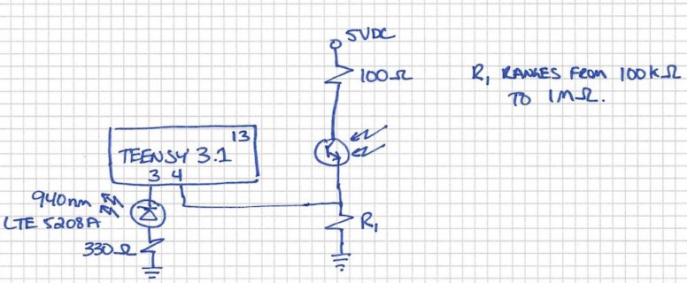
With the following circuit (see attachment), I am able to get a fluctuation in voltage of almost 0V to 0.1V… and if I increase the 100kohm to 1Mohm, then I get almost 0.5V to input pin #4 as measured on a MultiMeter… but this is not obviously enough to trigger the input.

I am not an expert by any means with electronics and have two questions:
  1. Is there any way to do this circuit with out a NPN transistor such as a 2N3904. Can one do this with one transistor given the input is transistor based, or do you need a darlington pair.
  2. What is the required voltage to trigger a digital input on the Teensy 3.1

The code for the program is quite simple and looks as follows, using the on board LED at pin 13 as an indicator for test purposes.
Code:
// Simple IR Test Program for LTE-5208A and LTR-3208E

const int LED = LED_BUILTIN;
const int IR_OUTPUT = 3;
const int IR_INPUT = 4;
const int WAITTIME = 500;

void setup() {
 pinMode(LED, OUTPUT);
 pinMode(IR_OUTPUT, OUTPUT);
 pinMode(IR_INPUT, INPUT);
}

void loop() {
 digitalWrite(LED, HIGH);
 digitalWrite(IR_OUTPUT, LOW);
 delay(WAITTIME);
 digitalWrite(LED, LOW);
 digitalWrite(IR_OUTPUT, HIGH);
 if(digitalRead(IR_INPUT)) {
   digitalWrite(LED, HIGH);
 }
 delay(WAITTIME);
}

circuit.jpg

Thanks for any help that you can provide! Rudy
 
Change the digitalRead to analogeRead https://www.arduino.cc/en/Reference/AnalogRead

And use an analog capable pin (14 and up) https://www.pjrc.com/teensy/pinout.html

with a 0.5V signal you should be able to use a if (analogRead(A0)>150) to drive the logic. That 150 is based on the max value being 1024 for a 3.3V input, so 1V = ~620 and 0.5 should read ~310. If you want you can get clever by reading with the LED off to measure background, and with it on to sense which may allow some basic range/shape detection.

Alternative is to add a transistor as an Amplifier, along with some bias components https://en.wikipedia.org/wiki/Bipolar_transistor_biasing

This will allow you to have more inputs, but complicate your circuit. In fact if you are trying to save component count try pinMode(A0,INPUT_PULLUP); with your light sensor connected to ground and A0/14 and no other components. Dynamic range will be pretty poor but may be 'good enough'.
 
I suggest that you use a modulated IR signal. A bare IR photodiode will yield poor range and lots of false/noisy signals.

Easy way, and conventional, is ...
Emitter is IR LED connected to an MCU bit that is driven by a PWM timer set for 50% duty cycle and 38KHz.
Software can turn this on and off as need be. In IR remotes, this 38KHz goes on and off per the serial data which is a start bit and a string of 1's and 0's at about 1200bps. Sometimes Manchester encoded. But for a simple proximity sensor, the signal can be always-on 38KHz to the IR diode.

The receiver should be one of the low cost 38KHz IR receiver modules. About $3. These have an optical filter, an amplifier, and a bandpass filter at 38KHz (or other less popular frequency).
It will output 1 or 0 based on presence or absence of 38KHz. It will be quite resistant to ambient IR from sunshine and some kinds of lighting.
Here's an example
https://www.sparkfun.com/products/1...yw9OQ1snBG6y0f66H_S4vqhvbT2g28z9NsaAuxK8P8HAQ
 
A few comments on IR detectors, if I may. First, I do recommend the integrated photodiode/preamp parts, they are much more sensitive than you could easily build from discrete components. BUT be aware most of these parts are optimized for IR data communication in presence of interfering signals. This design can work against you for simple beam-break or proximity-sensing applications, due to how their built-in AGC (automatic gain control) algorithms work.

Sparkfun is selling the Vishay TSOP38238 which the datasheet https://www.sparkfun.com/datasheets/Sensors/Infrared/tsop382.pdf shows as having "AGC2 / AGC8" type. If you have a constant 38kHz carrier, some of these parts will "track" the signal as it fades in and out so you may never get a beam break indication- at least that was my experience. At a minimum you should transmit short packets of 38kHz pulses with a significant "off" period between the pulse trains, not a steady carrier.

I don't know the precise parameters of the various Vishay AGC types but I have learned that what Vishay terms "AGC0" (fixed gain) is probably best for simple on/off proximity sensing, something like a TSSP4038 for example: http://www.digikey.com/product-detail/en/TSSP4038/TSSP4038-ND/3789836

They also have a "AGC P" type intended to give an output proportional to distance.
See also: http://www.vishay.com/docs/49009/49009_pl0438.pdf
 
Last edited:
Thanks to all that responded. With a few minor tweaks, specifically using the Analog I/O as recommended by GremlinWrangler, it got this working. The changes to the circuit posted above are as follows:
  1. Utilize pin #14 (analog A0) to detect signal from the LTR-3208E photo transistor (NPN) as an analog value rather than discrete on / off.
  2. Decrease the resistance of the resistor going to the LTE-5208A 940nm infra red (IR) emitters. Using a 100 ohm resistor instead of a 300 ohm resistor, noting the the LTE-5208A has a 1.2V drop and the output from Teensy pin #3 is just over 3.1V, increases the current from 6.4mA to 16mA. Now the light output is sufficiently bright. Note that I used an iPhone4 in selfie mode to confirm the IR is working.
  3. Change the circuit from one where the emitter and photo transistor are side by side and reflective to one where they are across from one another and create a beam that is broken when an object is in-between.

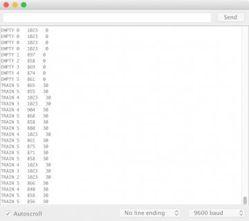
This design provides one with a 1023 analog input (max) when there is nothing present and drops it to about 820 when blocked. I added a counter that makes sure that, in this case a model train, is detected multiple times (TRAIN) and then the track stated to be empty after the infra red sensor has detected the track is clear multiple times (EMPTY)

The revised test code is as follows and a screen shot of the serial output is also attached.

Again, thanks for all your help.
Code:
// Test IR Logic

const int LED = LED_BUILTIN;
const int IR_OUTPUT = 3;
const int IR_INPUT = 14;
const int WAITTIME = 10;

void setup() {
  pinMode(LED, OUTPUT);
  pinMode(IR_OUTPUT, OUTPUT);
  pinMode(IR_INPUT, INPUT);

  Serial.begin(38400);
}

int val;
int i;
int flag1;

void loop() {
  digitalWrite(IR_OUTPUT, LOW);
  delay(WAITTIME);
  if(analogRead(IR_INPUT)>1000) Serial.print("ERROR ");
  delay(WAITTIME);
  digitalWrite(IR_OUTPUT, HIGH);
  delay(WAITTIME);
  val = analogRead(IR_INPUT);
  if(val>1000) i--;
  else i++;
  if(i>5) {
    flag1 = 30;
    digitalWrite(LED, HIGH);
    i = 5;
  }
  if(i<0) {
    flag1--;
    if(flag1<0) flag1 = 0;
    digitalWrite(LED, LOW);
    i = 0; 
  }
  if(flag1) Serial.print("TRAIN ");
  else Serial.print("EMPTY ");
  Serial.print(i);
  Serial.print("   ");
  Serial.print(val);
  Serial.print("   ");
  Serial.println(flag1);
  delay(WAITTIME);
}

teensy.jpg
 
If what you've got is doing what you want leave it be, but if you have ambitions to make it more capable some suggestions:

Work out how your error handling is going to work, you are printing serial messages but since this is handling model trains you may want to think of having some sort of abort system that halts operation, along with a mechanism to indicate which unit triggered the abort (few things are worse than fault finding a system where multiple units can trigger an e-stop, but no logs say which one).

What do you want it to do if a train stops in front of the sensor? Should that be an error condition?

You are using ints extensively and that's fine on a teensy, but if working with unsigned numbers https://www.arduino.cc/en/Reference/UnsignedLong make sure you watch for things like your
flag1--;
if(flag1<0) flag1 = 0;
line which can roll over into very high positive numbers rather than -1. An alternative is to 'if (flag1>0) flag1--;' which runs things down to zero and then stops. Not really a hassle unless you are heading towards memory limits.

Currently your code is 'blocking', which is a robust design for single operation but means everything stops while those delays happen. Consider if you want to have a single Teensy tracking multiple track sensors by running them as a state machine using
https://www.pjrc.com/teensy/td_timing_elaspedMillis.html
or more complex systems so that your loop runs through fast, checking if it's time to turn off or on a LED or make a sensor reading while also checking other sensors or control inputs.
https://learn.adafruit.com/multi-tasking-the-arduino-part-1/overview

As noted above there are many ways to get there from here, and if what you have works well enough then don't break it.
 
tried it with sunlight coming in a window directly or indirectly hitting the sensor?
Bandpass filter for IR with carrier (e.g., 38KHz) is the commonplace cure.
 
If your project is working well enough, probably best to quit while you're ahead....

But, if you wanted to try making this way more complicated, which *might* manage to reject stray light, one crazy idea might be to use the audio library. You'd drive the LED with PWM and use analogWriteFrequency to make it blink at some specific frequency in the middle of the audio band. Maybe 1 to 2 kHz. Then you'd connect the receiver to the A2 analog pin and use the audio lib adc object to receive the signal. In the audio design tool, perhaps connect the adc to one or more normal or biquad filters, which you'd configure as bandpass at whatever frequency you chose for the PWM. Then run the filter output to the peak detector object. Complicated as that sounds, it'd be quick and easy to draw in the design tool. Configuring the filters might take a bit of work. But in theory, assuming the sensor doesn't saturate with light, it might manage to be able to detect the PWM frequency even if the ambient light level changes pretty dramatically. Maybe.

But if it's working now, maybe leaving well enough alone is best?
 
I tested it in bright sunlight conditions and did not have any issues. I agree with GremlinWrangler's comments to use the state function so that the entire loop is not just held during the delay time. I appreciate comments about the audio library, but at this time will not likely pursue this avenue as the design is adequate for what I need. Thanks again, and I will keep you posted. Rudy
 
Status
Not open for further replies.
Back
Top