
Po Ting
Well-known member
Hello, and happy new year for everyone,")
I'm finally making my POV-POI into PCB
I use fritzing, as it is free and has no limit to board size.
and thanks for PJRC community for all the references and related data.
[Problems known]
before I print some PCBs and go on, I need some help from below,
1. I actually tried on some breadboards ,and I could't get a it working.
with the MKL04Z32_TQFP32 bootloader chip connect, I get an unknown USB device recognized by windows(win10), beeping randomly, but teensy loader doesn't respond to program button, a teensy 3.1 would not beep that much and works fine. the jumpers were connected with jumpers as in schematics.
with a total of 7, including ground and 3.3V.
Still working on this. But not going to solder them myself again. maybe a few PCB manufacture tries is better?
chips were from https://www.pjrc.com/store/ic_mkl02.html and soldered on TQFP breakout board with a momentary button.
connect lines were with same pins mentioned in the chip page .
Using a 40W solderer , not sure if chip damaged.
I'll upload the pictures of the boards as soon as possible.
2. Not sure if I should connect the crystall unused pins to ground or not.
3. Voltage resistor questions as mentioned below.
4. I may need power regulator choices.
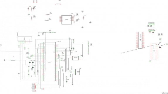
[Schematics]
https://drive.google.com/file/d/0B30_13TwRWWHSlRDUlZyTGM3elk/view?usp=sharing
Sorry for dirty schematics, I left the schematics unarranged. and sorry about about the pin names, there wasn't a library for the MK20DX
so I use atmege328 instead , as It gives the same TQFP64 layout, with some pins hidden in schematics.... should be fine if the pin numbers were correct.
the LED driver part(TLC5947) were working fine under breadboard with teensy3.1.
the power (TPS61200) was fine, or at least one of the tries was fine.
there's also a switch, to power from the battery to TPS61200 . not shown in schematics yet.
[POWERING]
the power (TPS61200) schematics were same to, I give a few tries on breakout board with all needed parts and most of them failed.
however, one of them worked and gives about 3.28Volts under USB power or Lithium battery (18650,3.7V)
that's a good news, maybe my solder skills just can't confront QFN10 package.
Also considering for a really Low LDO regulator like HT7333.
but not sure if the current supply will be enough, or not
http://www.digchip.com/datasheets/parts/datasheet/196/HT7333.php
the 3.3V power line was used for SD/MK20DX256 /,but not for lighting the LEDs(they were driven directly by battery power, and they works normally)
btw, I'm not sure, but MK20DX256 seems to give 1.1V internal analog reference, according to my testing value.
A voltage regulated to 3.3V would be fine to be the DEFAULT reference, or I need a bigger divider.
[Finally the main function]
Read .bmp from SD, store the whole picture to SRAM, then draw the pictures with TLC5947,
using software SPI. Could bit-bang a 36pixel/RGB up to 1000lines a second.
A0(p58) and A12(p11) to get volt reading from battery, and USB , while charging.
I tried 1.2M divider with teensy 3.1 and get incorrect results, so I lower the resistor values to 10K ohm.
Anyone have a better idea on this? A battery device should be when unpowered, 10K*2 seems to get a 200uA(under 4Volts) leakage and still acceptable.
-----------
thanks for everyone reading the topic, Happy new year!!!!!!!!!!!!
[References]
http://www.appfruits.com/2015/03/building-your-own-custom-teensy/
I'm finally making my POV-POI into PCB
I use fritzing, as it is free and has no limit to board size.
and thanks for PJRC community for all the references and related data.
[Problems known]
before I print some PCBs and go on, I need some help from below,
1. I actually tried on some breadboards ,and I could't get a it working.
with the MKL04Z32_TQFP32 bootloader chip connect, I get an unknown USB device recognized by windows(win10), beeping randomly, but teensy loader doesn't respond to program button, a teensy 3.1 would not beep that much and works fine. the jumpers were connected with jumpers as in schematics.
with a total of 7, including ground and 3.3V.
Still working on this. But not going to solder them myself again. maybe a few PCB manufacture tries is better?
chips were from https://www.pjrc.com/store/ic_mkl02.html and soldered on TQFP breakout board with a momentary button.
connect lines were with same pins mentioned in the chip page .
Using a 40W solderer , not sure if chip damaged.
I'll upload the pictures of the boards as soon as possible.
2. Not sure if I should connect the crystall unused pins to ground or not.
3. Voltage resistor questions as mentioned below.
4. I may need power regulator choices.
[Schematics]
https://drive.google.com/file/d/0B30_13TwRWWHSlRDUlZyTGM3elk/view?usp=sharing
Sorry for dirty schematics, I left the schematics unarranged. and sorry about about the pin names, there wasn't a library for the MK20DX
so I use atmege328 instead , as It gives the same TQFP64 layout, with some pins hidden in schematics.... should be fine if the pin numbers were correct.
the LED driver part(TLC5947) were working fine under breadboard with teensy3.1.
the power (TPS61200) was fine, or at least one of the tries was fine.
there's also a switch, to power from the battery to TPS61200 . not shown in schematics yet.
[POWERING]
the power (TPS61200) schematics were same to, I give a few tries on breakout board with all needed parts and most of them failed.
however, one of them worked and gives about 3.28Volts under USB power or Lithium battery (18650,3.7V)
that's a good news, maybe my solder skills just can't confront QFN10 package.
Also considering for a really Low LDO regulator like HT7333.
but not sure if the current supply will be enough, or not
http://www.digchip.com/datasheets/parts/datasheet/196/HT7333.php
the 3.3V power line was used for SD/MK20DX256 /,but not for lighting the LEDs(they were driven directly by battery power, and they works normally)
btw, I'm not sure, but MK20DX256 seems to give 1.1V internal analog reference, according to my testing value.
A voltage regulated to 3.3V would be fine to be the DEFAULT reference, or I need a bigger divider.
[Finally the main function]
Read .bmp from SD, store the whole picture to SRAM, then draw the pictures with TLC5947,
using software SPI. Could bit-bang a 36pixel/RGB up to 1000lines a second.
A0(p58) and A12(p11) to get volt reading from battery, and USB , while charging.
I tried 1.2M divider with teensy 3.1 and get incorrect results, so I lower the resistor values to 10K ohm.
Anyone have a better idea on this? A battery device should be when unpowered, 10K*2 seems to get a 200uA(under 4Volts) leakage and still acceptable.
-----------
thanks for everyone reading the topic, Happy new year!!!!!!!!!!!!
[References]
http://www.appfruits.com/2015/03/building-your-own-custom-teensy/
Attachments
Last edited:


