project problem!

Status
Not open for further replies.

edgar

New member
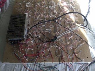
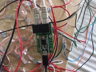
Hi, I have an array of 144 LEDs made in 6 strips of 24 LEDs connected to a teensy 3.2 and octows , I have connected 4 strips to an Ethernet cable and two strips to another Ethernet cable both with octo , when I send any test , it only illuminate me the two first of the block with 4 and the first of the block with 2, it is connected in the following way

Cable strip 1 orange
Blue wire strip 2
Strip 3 green wire
Brown wire strip 4
5 cable strip orange ( second Ethernet)
Strip 6 ( second Ethernet) blue wire.

What is the problem?
As would be the correct connection ?
Thank you
 
You haven't mentioned how you are powering the strips, and how the grounds are wired

https://learn.adafruit.com/adafruit-neopixel-uberguide/power
https://www.pjrc.com/teensy/td_libs_OctoWS2811.html

You need to have a separate high current 5V power source for those LEDs, then ensure the ground for the Teensy board is connected to the ground for the LED power supply so that:

Each strip 5V it connected to a suitable 5V power supply
Data line for each strip is connected to the Octo board on a coloured wire
Ground for the strip is connected to power supply AND to the white and coloured wire half of the pair in the cable.

There are also some questions you haven't answered around how your Teensy is powered, and if you have cut the trace to isolate USB power which may be impacting things here but first guess is that there isn't a shared earth on the LED strips.
 
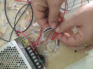
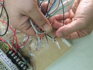
The conections are made this way , of each strip there is a data cable connected to a Ethernet colour cable and a ground cable to a Ethernet white cable and a ethernet colour cable like this

One of two strips have a 5v + and a ground connected to a power supply

Is needed to connect octo directly to a power supply? the power supply is a 150 w 5v

thanks for the last answer
image1.JPGimage2.JPGimage3.JPGIMG_0291.JPG
 
If the Teensy has a USB cable in it can get power from there, and you DON'T want the 5V line connected till you've done some more thought on keeping USB and LED power seperate.

What matters is that all the twisted pair wires are connected so they have grounds connected via that end.

The pictures are all of the items needed, but aren't showing quite enough pixels to work out which wires are going where, especially in that last one.

If you have access to an oscilliscope a useful test is working through your power, ground and data connections but assuming you don't have one handy?

If not some testing:
Confirm you can load blink to the Teensy
Connect a multimeter up to your PSU gnd and measure:
Strip gnds (should be 0V)
End of strips (should be >0.5V)
Octo board Gnd (should be ov)
Strip 5V (5V)
Strip ends (>4.5V)
Teensy 5V (5V)
If this isn't finding anything then modify blink to toggle the following pins:
2,14,7 and 8
Either all at once by adding a bunch more pin definitions or by just modiging the pin constant one at a time. Then using the multimeter confirm your data lines toggle 0 and 5V.

If none of this has found a wiring problem then it's time to load up the neo pixel library and test one strand at a time: modifying the pin in use in the neopixel strand test to us 2, 14 7 and 8 in turn and see if any of the strips go through the demo.
 
Hi,

I have found that all led strips current reaches them, and this ok.

would like to know how to make a modify blink to toggle the following pins:
2,14,7 and 8

the data connections I have made a CAT6 568c.2 are like those of CAT6 568b

thank you for your help
 
Either change
const int ledPin = 13;

to be a different number, or go the whole hog and

const int ledPin1 = 2;
const int ledPin2 = 14;
const int ledPin3 = 7;
etc

Then duplicate the setup pinMode lines and the digitalWrites
If this isn't making sense then you really need to read
https://www.arduino.cc/en/Tutorial/Blink

Also suggest
https://en.wikipedia.org/wiki/Voltage
https://en.wikipedia.org/wiki/Electric_current

Because your 'I have found that all led strips current reaches them' could mean several things.
Did you really measure the current in amps flowing through the LEDs, or did you measure a voltage in volts present AT the LEDS? It's important since if you had measurable current flow with LEDs not working there is something badly wrong. And the presence of one does not imply the other.

Sorry to be sending you off to read stuff, but there is a bunch of core concepts here to sort out before you start on more complex parts of this project.

Also unsure what you mean by 568. Wiring should be as per https://www.pjrc.com/store/octo28_adaptor.html but even if you get the colours mixed up, as long as the colour/white wires are to ground and colours go to data pins they should light up. Pattern might be mixed up if a data wire is crossed but it will at least light up.
 
Status
Not open for further replies.
Back
Top