Best Practice soldering for Teeny 3.X plus Audio Shield and Breadboard

Status
Not open for further replies.

Davidelvig

Well-known member
I've soldered a Teensy to an Audio Shield in one prototype, and similar to the photo attached:
- Teensy on top - with a piece of electrical tape sandwiched between that and the Audio Shield
- socket on top, with pins through the bottom sufficient to stick in breadboard
- audio out as stick-up pins from the shield, and mic in as bent pins sticking out sideways under the USB jack.
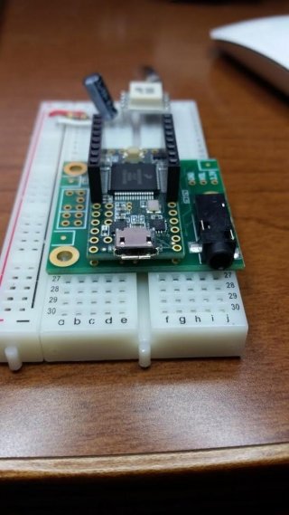
Teensy and Audio Shield.jpg
You can see how it covers the breadboard too thoroughly, so when in use, I have more patch wires than I'd like (rather than low-profile, on-the-breadboard wires.

I also have a couple of other Teensy 3's with pins down only (great for breadboarding with the narrow dimension).

This photographed option works well enough for me, but before I solder my next Teensy plus Audio Shield, I'd like to do a reality check.

What are others doing to make Teensy/Audio assemblies that are solidly bonded, yet flexibly deployed (e.g. on a breadboard?)

(Note in the photo, this is just a thrown together (non-soldered) example. My in-use version has end-to-end sockets, and a few extra audio shield pins soldered as well)

Thanks
Dave
 
I hate soldering and in fact I have a blister on my left index finger from an encounter with the soldering iron last night.

Depending on what I'm doing, I will do different things.

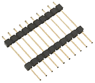
For the audio shield, I soldered a Teensy with long pin female headers. So far, I haven't been able to find headers with 14 pins. The best I've found is at dipmicro.com, they have 18-pin, 20-pin, and 40-pin headers: http://www.dipmicro.com/store/HDR18X1FL. You solder this into the Teensy and if desired cut off the excess. Or with 18/20 pin variants, you can solder wires connecting some of the underneath pads for the extra holes.

The for the audio shield, I used long pin male pins (https://www.adafruit.com/products/400), or you could use more of the long pin female headers.

In my current build, I'm using an Adafruit Audio FX board, and I'm soldering the FX board to one side of this protoboard, and the Teensy to the other. If I don't manage to wreck things, I'll try to post some pictures: https://www.tindie.com/products/wikistik/small-prototyping-board/. I'm using a wide dip 28 pin holder for the Teensy, and female headers for the Audio FX board, so that I can remove each board, and put it back on a breadboard. On the Audio FX board, I don't use all of the pins, so I'm mounting an optocoupler and level convert in the unused space.

I also like the Adafruit mint-tin protoboards:
 
Last edited:
Also, I'd love to access the additional pins on the bottom...
Best practice there (for this case?)

I had originally grouped these in the Teensy Quick Reference post: https://forum.pjrc.com/threads/25395-Teensy-Quick-Reference-Code-Examples-Tips-and-Tricks/page2, but that doesn't include the newer boards.

Here are some other boards to access the bottom pins (I have these, but I haven't used them yet):

If you are using the Talldog, Petit Studio, or KurtE's boards, you may want to look at this thread from Jimmayhugh that gives suggestions on how to solder the connector for the underneath pins: https://forum.pjrc.com/threads/26071-Using-all-Teensy3-x-pins-with-a-socket
 
Last edited:
I got long pin female headers in a 100 pack - half were 8 and half were 6 pin - oddly enough that comes out to 14 in some combination.

http://www.amazon.com/Stackable-Headers-Arduino-compatible-development/dp/B0197J23WW

That link is what I mean - but not what I got. I saw another 100 pack that was $28 - but I didn't pay half that. The pins are thin and wimpy - but I've used and abused and cut them with reckless abandon since I got 50 of each. They bend nicely (once) and offer good utility.
 
Thanks, folks! All good stuff.
I have a few of those 6&8 pin stackables. Interestingly, mine require shaving one end or the other for them to fit together end-to-end when inserted into the Teensy.

Perhaps FrankB is producing and selling the under-pin board?
Perhaps I'll try my first oshpark purchase.
 
When I ordered mine in November, it was $3.45 for three of FrankB's boards, and $8.30 for three of the CPT boards. I ordered them on November 11th, and they were sent via USPS on November 19th. It depends on how many orders OSH park has, as they have to make a full panel before doing the order.

In terms of the 6 & 8 pin stackable headers, those are fairly common for Arduino boards. If you are willing to shave down one end, they would work being adjacent. Unfortunately for my current project, due to the pin layout of the Audio FX board, I could have used a 7 pin female header, but I had 2, 3, 4, 5, 6, and 8 pin headers, but I didn't need access to a middle pin, and used 2 3-pin headers.
 
I have a few of those 6&8 pin stackables. Interestingly, mine require shaving one end or the other for them to fit together end-to-end when inserted into the Teensy.
These headers are very expemsive in Germany. The 100pcs pack for 10$ might not be shipped to Germany (the selling companies won't offer it - its not shipped by amazon), so I have to pay at least a price around 70$ to 80$ - that's not quite satisfying.

For the breadboard, I lift the PCB with a stack type header, like Paul also recommends:

header-2.png

And concerning the "shaving": Well, just unpack your Dremel and all is fine ... works well. see here:

header.png
 
Last edited:
Perhaps FrankB is producing and selling the under-pin board?


No, that would be too much work and effort.


Perhaps I'll try my first oshpark purchase.
Good choice :)

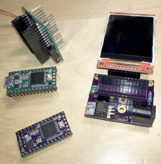
btw, i soldered a Teensy 3, the connectorboard, the memoryboard, the audioboard and an additional (unpublished) display-board (to which a ili9341 is soldered) with double-length pinheaders (cheap from amazon germany). It's very compact and still "teensy" this way..
On the side next to this construction, an ESP8266 is installed.

but un-solder any of these components is "mission impossible" :)
 
Last edited:
btw, i soldered a Teensy 3, the connectorboard, the memoryboard, the audioboard and an additional (unpublished) display-board (to which a ili9341 is soldered) with double-length pinheaders (cheap from amazon germany). It's very compact and still "teensy" this way..
On the side next to this construction, an ESP8266 is installed.
.
I assume you aren't using the SD card, using software bit-banging SPI, or perhaps use something like i2c instead of spi to talk to the ili9341?

but un-solder any of these components is "mission impossible" :)
I'll bet.

One thing I've thought about is stacking 30-pin prototype boards (like https://www.adafruit.com/products/723 or https://www.adafruit.com/products/1609). Mount the Teensy on the bottom board. Put female headers on the outside for both sets of 14 rows. For intermediate boards, use stacking headers (either 18 pin or 6/8 pin if you grind down one edge), so that you can stack another board on top of it. On the top board (such as the Audio Shield, which doesn't allow such stacking), just put normal male header pins.

This way, you pass all 28 pins through, and each layer now has 32 pins to use for prototype space (2 rows of 16 pins). You might consider adding some headers at the other end of the board to make things more stable.

Other prototype boards I've seen:

I've seen some other boards also, but I don't recall where.
 
Last edited:
Oh, yes, the audioboard uses the SPI for the SD-Card and the optional JEDEC-Mem SOIC-8 "socket" (this is the only option i did not use).
But this no problem, because every SPI-device is adressable with the Chipselect-signals.


More challenge is the software because all this SPI (6x SPI for the Memoryboard, touch + 2xCS for the display, SD-Card...) need some time to transfer the data... even when running at full speed (20/30/25 Mhz) , so there is not much time left if you need to use all of these devices at full speed and still need a high amount of left cpu-cycles (in my case decoding mp3 or aac from a internet-datastream (esp8266) )
DMA for the memoryboard was very useful.
 
Last edited:
Ok, cool. I thought the Audio Shield used all of the SPI interfaces, but I haven't used SPI so far.

There is a single SPI data bus on T_3's. Use of the bus is 'by invitation' of the CS pin - all compatible hardware responds/yields per the hardware spec, and as long as the driver software for each device follows the PJRC/Transaction spec each software transaction sets gets exclusive access.

The odd thing about the Audio Shield is "SCLK and MOSI are used at alternate locatoins" meaning any driver must allow pin movement to the alternate SPI pins - and not violate the transaction model rules.
 
Given the discussion of the underneath pins and multiple SPI devices, etc. I wonder who will first run into one or more limits of the so-called Teensy 3.1++ board.

From the discussion:
  • 48 through hole pins
  • 5 serial ports, only 2 (or 3?) with RTS/CTS
  • 2 SPI ports
  • 3 i2c ports
  • 2 DACs

FWIW, the project I'm currently working on is using 18 of the 24 data pins along the outside edges. If I used the Audio Shield instead of the Audio FX card, I would have one pin left. So, I have the feeling that sooner or later, I'm going to be soldering to get access to the underneath pins.
 
My project uses all of the touch pins on the top side left over after the Audio Shield uses what it must for various communications protocols.
Getting at the 3 touch pins on the back is a key reason for my getting FrankB's connector board from Oshpark.
I could see the need for the 48-through-hole board. Of course... we're like a gas... expanding to fill our container!
Thanks, all for the great discussion.
 
Well, Paul had to in order to use the I2S pins, SCK (i.e. pin 13) is the I2S RX pin, MOSI (i.e. pin 11) is the I2S MCLK. I don't believe there are any alternate pins for I2S.

Indeed - by 'odd' I meant only unique requirement for use - not that it was any way arbitrary - I edited out the I2S part in my reply. I was just trying to confirm my understand of SPI I just came by as I look to make one of the PJRC OSH ILI9341 display boards stackable with my Audio Board.

I found I need to make two simple trace cuts and two small bridges to rejoin the alternate pins - and finding it very hard to jump <1mm to pin hole rings from an uncovered trace - even with the coating in between scratched off?
 
While waiting for this board, I'm curious if there are boards with a kind of a "patchfield" which allows to reassign SPI or I2S pins without causing a ravel of colored wires ... nothing found yet ...
 
curious if there are boards with a kind of a "patchfield" which allows to reassign SPI or I2S pins without causing a ravel of colored wires ...

I've not seen such a thing, but it sounds like a really interesting idea. Maybe someone will give a try and (hopefully) share on OSH Park?
 
I'm thinking about an solution ... This would be ideal: ADV3200/ADV3201, but ... hm ... well, a little oversized (in Germany we speak about "to shoot sparrows with canons") :D - the price is about 128 EUR (digiKey), the size could be bearable. But it does what we want and a breakboard with this Crossswitch will enable any Teensy to define it's pinout (nearly) arbitrary. But perhaps a board with a bunch of micro switches aligned in a matrix could do the job as well ...
 
I've not seen such a thing, but it sounds like a really interesting idea. Maybe someone will give a try and (hopefully) share on OSH Park?
I suspect the ADV3201 is overkill, and of course the price puts it out of the reach of most people. Given on the Teensy 3.x, you have fixed choices (and generally only 2 pins), it would be a lot simpler to have a manual breakout, where you use jumpers.

KurtE's breakout shield https://github.com/KurtE/Teensy3.1-...er/Teensy Shield Arduino Headers Through Hole breaks out all of the pins into data, power, and ground pins. With each group of 5 pins, there is a manual 3 pin section that you would use a 2 pin jumper to select which voltage to use for the pins (so that you can have some pins with 5v power rails and some with 3.3v power rails). He also has jumpers so that you can selectively add resistors to given pins.

I imagine for each of the buses you would have a row of the pins for the functionality, such as power, ground, TX, RX, RTS, CTS for Serial1 and then parallel rows for the jumpers for each pin (solder jumpers to save space, through hole jumpers in groups of 3 for flexibility). So for Serial1, you would need jumpers for:
  • Pin 0 and 21 (A7) to RX;
  • Pin 1 and 5 to TX;
  • Pin 6 and 19 (A5) to RTS;
  • Pin 18 (A4) and 20 (A6) to CTS.

For extra credit, you would have a parallel row of pins where you do protocol specific level shifting (i.e. serial/spi would only need one way shifting, while i2c needs to be able to shift both ways).

I imagine for SPI, you would want selectors for MISO/MOSI/SCK, and then bring out several 2x3 connectors for several CS pins.
 
Last edited:
Status
Not open for further replies.
Back
Top