Does FreqMeasureMulti work with Teensy 3.0

Status
Not open for further replies.
I tried giving FreqMeasureMulti a spin using a Teensy 3.0. Using the example, I wasn't able to detect any pulses.

I'm using hall effects sensors within a brushless motor. I've verified that the sensors are working. Doing a simple analogRead on pin 6 shows the values change predictably as I rotate the rotor.

Is it possible that the Teensy 3.0 isn't compatible with FreqMeasureMulti?
 
I spent some time comparing the manuals for the MK20DX128 (Teensy 3.0) and the MK20DX256 (Teensy 3.1) and can find very little difference between the two chips. Granted, I'm digging into docs that are on topics pretty foreign to me. That said, I can't see why the FreqMeasureMulti lib wouldn't work for Teensy 3.0.

From what I can tell, on this line of code we're selecting the alternate pin function of the MK20DXxx chip. For pin 6, we're saying "use ALT4, aka FTM0_CH4". Both chips have the same mappings, so I'm guessing that the reason it's not working isn't because of the differences in chips.

As far as pin 6 goes, the only difference I could find between the two docs is that the MK20DX256 has an ALT5 of FB_AD2, while the MK20DX128 has no ALT5. I have no idea what FB_AD2 is (the only mention of FB_x anything is in section 10.3 of the MK20DX256 manual).

So I'm going to revisit my tests and try to understand why the example code doesn't work.
 
As far as pin 6 goes, the only difference I could find between the two docs is that the MK20DX256 has an ALT5 of FB_AD2, while the MK20DX128 has no ALT5. I have no idea what FB_AD2 is (the only mention of FB_x anything is in section 10.3 of the MK20DX256 manual).

I think AD2 is the second ADC that's new in the 3.1.
However, do you know that your input signal variation is strong enough to trigger whatever it is that the frequency detection is looking for?
Do you have an oscilloscope where you can look at it?
 
It really should work on Teensy 3.0, but honestly, I haven't tested.

You're running the 3 input example that comes with the library, right?

If you're still having trouble, please let me know and I'll set up a test here with a Teensy 3.0. Maybe there some small detail I overlooked?
 
However, do you know that your input signal variation is strong enough to trigger whatever it is that the frequency detection is looking for?
Do you have an oscilloscope where you can look at it?

I haven't tried an oscilloscope, though it's something I can try.

What's interesting is that I can use the same inputs with the Encoder lib just fine.

As I mentioned in my first post, I'm measuring the values from hall effects sensors as the rotor turns. I have three total sensors, but if I treat a pair of those sensors like an encoder it works just like a quadrature encoder would. I haven't dove into the Encoder lib to see how it measures a "tick", but it stands to reason it's a pretty big clue.

For now, treating a pair of the sensors as an encoder works fine. I was able to measure RPMs of the motor using this (and a bunch more, obviously):

Code:
  // within loop()
  if (rpmMetro.check() == 1) {
    current_rpm = (hall_a_b.read() / TICKS_PER_REV) * 600;
    hall_a_b.write(0);
  }

Using Metro, every 100ms I check the encoder value, and divide it by the number of "ticks" per full revolution. TICKS_PER_REV was derived by rotating the rotor by hand 360 degrees while printing the value of hall_a_b.read(). I then reset the encoder since I'm not concerned with the actual position or even rotation direction. This also avoids having the encoder value reach insane numbers, and means I don't need to set a bunch of variables to later do math on to see how many ticks have accumulated since I last checked.

While it works in simple tests, I don't think it's as accurate as it could be. And since this motor spins well above 25,000 RPM, the errors will come quickly. I think measuring frequency of a single hall sensor (or all three to see if they agree) would produce fewer errors over time. So I'm still interested in making it work, but I'm stumped as to why it won't for now.
 
I just tested here on a Teensy 3.0. Works fine.

fmm1.jpg

fmm3.png

fmm2.jpg

file.png

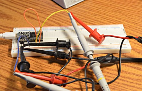
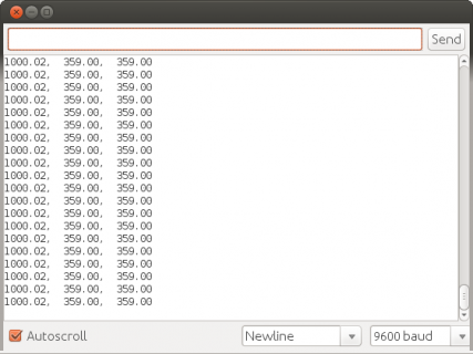
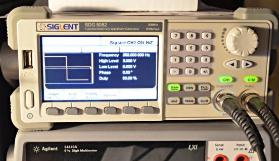
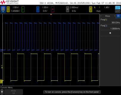
Admittedly, I used a 2-output function generator and just connected a wire between pins 9 and 10, so both saw the same input. I did test shorting to pin 6 instead, and indeed it appears to be measuring whichever signal where it's connected. It also picks up and measures 60 Hz AC coupled noise nicely when I touch the floating wire, while the other 2 continue measuring the function generator signals.

Unless there's reason to believe there's a problem, I'm not planning to rig up a true 3+ signal test, since I only have one convenient 2-output function generator.
 
One very minor issue I did find is FreqMeasureMulti has a library.properties file which I just copied from FreqMeasure, but never updated. That causes it to not appear in Arduino's File > Examples menu. I've updated the file on github. No actual code was changed, just this metadata file was updated.
 
Unless there's reason to believe there's a problem, I'm not planning to rig up a true 3+ signal test, since I only have one convenient 2-output function generator.

I'll hook up the oscilloscope and do some more testing this afternoon.

Even before knowing about your pretty comprehensive tests I was becoming convinced it must be something on my end. The Encoder library isn't doing anything all that special when it comes to reading those pins.
 
I haven't been able to test as thoroughly as I would have liked, but I was able to hook up my cheap single channel oscilloscope to one of the sensors on pin 6.

I'm not experienced enough to be able to say what the signal levels are, but it's very obvious the sensors are doing something. I've included a video that might be more useful to those with more experience. The question I have when I'm watching these signals is "are they jumping high enough to be detected by the FreqMeasureMulti lib?"

Also, thinking about, is there a minimum frequency? I've not tested the lib when running at speed. I've only been doing manual testing as seen in the video.

 
Well, quite by accident I got it working.

I'll admit, I only vaguely know why it works now, but I'll share what I did for those who do:

While testing the sensors at higher speeds (and not seeing any results), the example code began working for whatever pin I had my oscilloscope hooked up to, essentially connecting 5v to that pin. Assuming the oscilloscope was introducing some resistance I decided to add 4.7k resistors for each sensor pin, each connected to the Teensy's Vin pin, and lo and behold it all worked.

Here's the before:

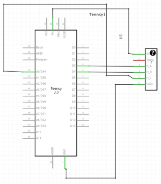
halls_before.png

And after:

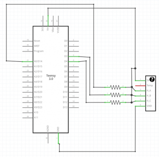
halls_after.png

So what's happening here?
 
An oscilloscope is typically modeled as a 1-10 MOhm resistor in parallel (not series) and a 5-50 pF capacitor in parallel (again, not series.)
That second diagram cannot possibly be correct, because it would short Vcc to the hall sensor output.

Perhaps the hall sensor outputs are open-drain, and actually need a pullup?
 
That second diagram is indeed how it's wired up in reality. I don't have much info on the wiring for the hall sensors, but I was able to find this from Google. These sensor harnesses are, or were, standard for radio controlled car racing motors. I don't recall the actual name of the standard, but I was at one time able to find this:

Code:
Pin #1 – black wire, ground potential (minus)
Pin #2 – orange wire, sensor phase C
Pin #3 – white wire, sensor phase B
Pin #4 – green wire, sensor phase A
Pin #5 – blue wire, motor temperature sensing, 10 k NTC
(other end of sensor is on ground potential, pin #1)
Pin #6 – red wire, sensors feeding, +5.0 V ± 10%.
(supply voltage for sensors provide controller, don´t connect external voltage !)

I would have thought it would short the hall sensor output as well, and I've rebuilt triple checked this controller a dozen times making sure I wasn't doing anything stupid while trying to get to the bottom of why I couldn't measure those signals. This last iteration with resistors between Vcc and the sensor pins is the only time I've ever seen it work with the FreqMeasureMulti lib.

I'm going to try using the same setup with a Teensy 3.1 (sans resistors first). Does it enable internal pullups by default while the Teensy 3.0 has none at all? Maybe?
 
Your second diagram shows VCC going straight to the hall sensor outputs, shorting all of the outputs.
Then there is a resistor from VCC to each of the inputs on the Teensy.
I e, the Teensy can only show "high" on all three sensor pins, and the sensor pins all see full VCC (and are shorted together.)
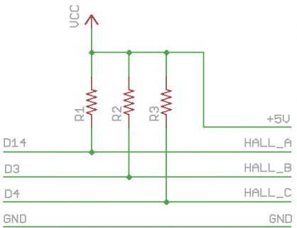
I really don't think that's how you wired it. It sounds from your description as if you wired it like so:
20160209-hall-sensor.png

If this is actually how you wired it, then it would make sense if the sensor outputs are open-drain outputs.
You could then also just use the built-in pull-ups in the Teensy itself.
However, it wouldn't make sense why the oscilloscope would make it work then -- it's just a resistor and a capacitor to ground, rather than pulling up.
 
Status
Not open for further replies.
Back
Top