Need help with FTM settings

someteen

Well-known member
Hello,

I need some help to configure the FlexTimer module for this particular scenario:

I need to drive some power MOSFETs (H-bridge configuration) using PWM signals with unipolar modulation scheme, to generate a high power AC signal (50 Hz).

I need two independent output signals (one for each H-bridge legs) as I have a separate hw circuit to get the complementary signals with inserted dead time.

Let's presume the switching frequency is 10 kHz and the modulating frequency is 50 Hz.

The H-bridge should be driven like that:

During a 10 ms interval (50 Hz half wave), one leg will be tied to ground (PWM duty-cycle = 0) while the other one will be driven with a variable duty-cycle PWM signal (100 steps x 100 us = 10 ms).

After every 10 ms cycle, the PWM signals have to be switched (the first one will output variable duty-cycle PWM while the second one will generate a steady signal (duty-cycle = 0)).

The duty cycle value should be read from a sine wave look-up table (100 steps).

Every time the timer is restarting (overflow), I need it to fire up an ISR to do the rest of stuff (ADC readings, duty-cycle correction, serial communication).

The FTM channels should be edge-aligned.

So I need the following settings for the FTM(0):

(1) set the FTM frequency to 10 kHz
(2) define two PWM outputs, edge aligned
(3) fire up an ISR every 100 us (timer overflow)

Inside that ISR:

(4) set the next pulse duty-cycle value (from the look-up table)
(5) (after 100 iterations) switch the PWM signals output

Could someone write a simple sketch to start with? I really don't know how to manage steps (3) to (5).

I don't want to put anything else in the main loop() or to use any other interrupts. I want the PWM signals to be as jitter-free as possible.

Thank you very much for your time.
 
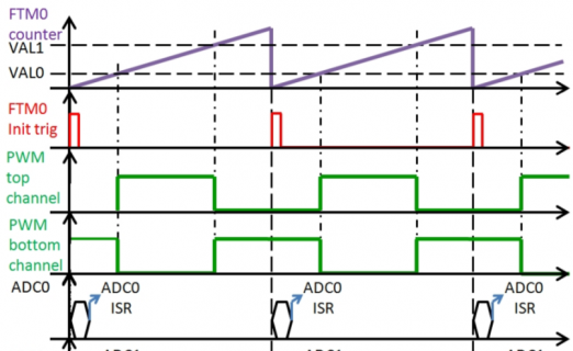
I forgot to mention that I found this app note on Freescale (NXP) website: FlexTimer and ADC Synchronization for Field Oriented Control on Kinetis.

It pretty much does what I need to do except the PWM duty-cycle is constant and it only trigger the ADC measurements on timer overflow. It also use center-alignment pulses but that's not an issue.

This is the actual timming I'am looking for:

FTM syncro.png

(except the PWM bottom channel should be low during 100 cycles then the PWM top channel will be low for another 100 cycles and so on).

Here is some sample code from that app note:

- FTM initialisation:

Code:
FTM0_MODE |= FTM_MODE_WPDIS_MASK; /* Disable write protection */
/* FAULTM = 1 - Fault control is enabled for all channels,
FTMEN = 1 - all registers are available for use with no restrictions.*/
FTM0_MODE |= FTM_MODE_FAULTM_MASK | FTM_MODE_FTMEN_MASK;
/* setting for Center Aligned PWM in Combine Mode *
FTM0_MOD = MODULO/2 - 1; /* Set PWM frequency; MODULO = 25 MHz/10kHz=2500 */
FTM0_CNTIN = -MODULO/2;
/* CTNMAX = 1 - PWM update at counter in max. value */
FTM0_SYNC |= FTM_SYNC_CNTMAX_MASK;
/* SWSYNC = 1 - set PWM value update. This bit is cleared automatically */
FTM0_SYNC |= FTM_SYNC_SWSYNC_MASK;
/* Disable all channels outputs using the OUTPUT MASK feature.*/
FTM0_OUTMASK = FTM_OUTMASK_CH5OM_MASK | FTM_OUTMASK_CH4OM_MASK
| FTM_OUTMASK_CH3OM_MASK | FTM_OUTMASK_CH2OM_MASK
| FTM_OUTMASK_CH1OM_MASK | FTM_OUTMASK_CH0OM_MASK;
/* COMBINE = 1 - combine mode set, COMP = 1 - complementary PWM set,
DTEN = 1 - deadtime enabled, SYNCEN = 1 - PWM update synchronization enabled,
FAULTEN = 1 - fault control enabled */
FTM0_COMBINE = FTM_COMBINE_SYNCEN0_MASK | FTM_COMBINE_DTEN0_MASK
| FTM_COMBINE_COMP0_MASK
| FTM_COMBINE_COMBINE0_MASK
| FTM_COMBINE_SYNCEN1_MASK | FTM_COMBINE_DTEN1_MASK
| FTM_COMBINE_COMP1_MASK
| FTM_COMBINE_COMBINE1_MASK
| FTM_COMBINE_SYNCEN2_MASK | FTM_COMBINE_DTEN2_MASK
| FTM_COMBINE_COMP2_MASK
| FTM_COMBINE_COMBINE2_MASK;
/* Dead time = 2 us for 25 MHz core clock 2us/40ns */
FTM0_DEADTIME = 50;
/* Initial setting of value registers to 50 % of duty cycle */
FTM0_C0V = -MODULO/4;
FTM0_C1V = MODULO/4;
FTM0_C2V = -MODULO/4;
FTM0_C3V = MODULO/4;
FTM0_C4V = -MODULO/4;
FTM0_C5V = MODULO/4;
/* ELSnB:ELSnA = 1:0 Set channel mode to generate positive PWM */
FTM0_C0SC |= FTM_CnSC_ELSB_MASK ;
FTM0_C1SC |= FTM_CnSC_ELSB_MASK ;
FTM0_C2SC |= FTM_CnSC_ELSB_MASK ;
FTM0_C3SC |= FTM_CnSC_ELSB_MASK ;
FTM0_C4SC |= FTM_CnSC_ELSB_MASK ;
FTM0_C5SC |= FTM_CnSC_ELSB_MASK ;
/* Enables the loading of the MOD, CNTIN, and CV registers with the values of their write
buffers. */
FTM0_PWMLOAD = FTM_PWMLOAD_LDOK_MASK ;
/* Enables the generation of the trigger when the FTM counter is equal to the CNTIN
register. */
FTM0_EXTTRIG |= FTM_EXTTRIG_INITTRIGEN_MASK;
FTM0_MODE |= FTM_MODE_INIT_MASK;
/* Default ADC trigger source is PDB. In case you need ADC triggered directly from FTM add
next two lines. ADC0ALTTRGEN = 1 - alternate trigger for ADC, ADC1TRGSEL = 0x8 - FTM0
trigger*/
//SIM_SOPT7 |= SIM_SOPT7_ADC0TRGSEL (0x8) | SIM_SOPT7_ADC0ALTTRGEN_MASK; /*FTM0 triggers
ADC0*/
//SIM_SOPT7 |= SIM_SOPT7_ADC1TRGSEL (0x8) | SIM_SOPT7_ADC1ALTTRGEN_MASK; /*FTM0 triggers
ADC0*/
Set system clock as source for FTM0 (CLKS[1:0] = 01) */
/* Set system clock as source for FTM0 (CLKS[1:0] = 01) */
FTM0_SC |= FTM_SC_CLKS(1);
/* PORTs for FTM0 initialization */
PORTC_PCR1 = PORT_PCR_MUX(4); /* FTM0 CH0 */
PORTC_PCR2 = PORT_PCR_MUX(4); /* FTM0 CH1 */
PORTC_PCR3 = PORT_PCR_MUX(4); /* FTM0 CH2 */
PORTC_PCR4 = PORT_PCR_MUX(4); /* FTM0 CH3 */
PORTD_PCR4 = PORT_PCR_MUX(4); /* FTM0 CH4 */
PORTD_PCR5 = PORT_PCR_MUX(4); /* FTM0 CH5 */

- other settings and the ADC interrupt routine:

Code:
/* enable clock for peripherals */
SIM_SCGC5 |= SIM_SCGC5_PORTA_MASK | SIM_SCGC5_PORTB_MASK | SIM_SCGC5_PORTC_MASK
| SIM_SCGC5_PORTD_MASK | SIM_SCGC5_PORTE_MASK ;
SIM_SCGC6 |= SIM_SCGC6_FTM0_MASK | SIM_SCGC6_PDB_MASK
| SIM_SCGC6_ADC0_MASK;
SIM_SCGC3 |= SIM_SCGC3_ADC1_MASK ; /* enable interrupt ADC0, ADC1 */
NVICISER1 = 0x06000000;
/* Enable PWM outputs of FTM0 and */
FTM0_OUTMASK = 0;
/* Enables the loading of the MOD, CNTIN, and CV registers with the values of their write
buffers. */
FTM0_PWMLOAD = FTM_PWMLOAD_LDOK_MASK;
void ADC0_IRQHandler(void)
{ /* toggle PTC18 to see when ADC interrupt is called */
GPIOC_PTOR = 1UL << 18;
/* Save the results and clear the COCO flag */
if ( ADC0_SC1A & ADC_SC1_COCO_MASK )
result0RA = (unsigned short) ADC0_RA;
/* delete next two lines if the two-time measurement per PWM period is not required */
else if ( ADC0_SC1B & ADC_SC1_COCO_MASK )
result0RB = (unsigned short) ADC0_RB;
}
void ADC1_IRQHandler(void)
{ /* toggle PTC18 to see when ADC interrupt is called */
GPIOC_PTOR = 1UL << 18;
/* Save the results and clear the COCO flag */
if ( ADC1_SC1A & ADC_SC1_COCO_MASK )
result1RA = (unsigned short) ADC1_RA;
/* delete next two lines if the two-time measurement per PWM period is not required */
else if ( ADC1_SC1B & ADC_SC1_COCO_MASK )
result1RB = (unsigned short) ADC1_RB;

It uses PDB to trigger the ADC ISR but I would not need that.
 
It's easy to see that my background is not exactly embedded software. ;)

I guess it was kind of noob question, but that's what I was actually looking for:

Code:
void ftm0_isr(void)
{
  // my stuff goes here;
}

I though I had to declare it somehow (like you do with IntervalTimer.begin(interval, hook) but you just need to write it somewhere in your program.

Ok, now that I got my ISR, how to update the PWM duty cycle for the next pulse? Do I need to write to this register:

Code:
FTM0_C0V = nextDutyCycle; // the new PWM duty cycle for output 0  
FTM0_C1V = 0; // duty cycle is 0 for output 1

Do I have to write another register to actually load those new values?
 
Give it a try and see.

Unfortunately, I'm on a highway right now. ;)

Thanks for the tips! So do I have to (re)set status & control register before/after updating CnV registers?

Code:
FTM0_SC=0x00;
FTM0_C0V = nextDutyCycle; // the new PWM duty cycle for output 0  
FTM0_C1V = 0; // duty cycle is 0 for output 1
FTM0_SC=0x08;
 
Unfortunately, I'm on a highway right now. ;)
That's some crazy multitasking :)

So do I have to (re)set status & control register before/after updating CnV registers?
In that particular case it seemed we had to. Although everything in the datasheet seemed to suggest otherwise. Try it without first. As you're not using any of the combine modes it should work without
 
I've just found somewhere that adding "FTM0_SYNC |= 0x80;" after updating CnV register should do the job. I just can't wait to test it.
 
Bit 7 of FTM0_SYNC register is SWSYNC.

By setting this bit to "1" you're actually performing a PWM software synchronization.

That's it, "FTM0_SYNC |= 0x80;" forces this bit to "1".

But there's also bit 1 (CNTMAX) of FTM0_SYNC register which might be set at the init time.

If CNTMAX is "1", the selected loading point is when the FTM counter reaches its maximum value (MOD register).

So if you set this bit to "1", a synchronization is performed every time the FTM counter reaches MOD (end of PWM cycle) value hence you don't need to set SWSYNC bit after each CnV update.
 
Last edited:
Seems like there's no "Timer Overflow Interrupt" generated.

Code:
void ftm0_isr(void)
  {
  digitalWriteFast(pin_LED, HIGH);
  }

The above ISR is not triggered though I've enabled it in the corresponding register:

Code:
FTM0_SC = 0x48;

0x48 is "01001000", that means bit 6 (TOIE, "Timer Overflow Interrupt Enable") is set to "1" and 4-3 bits (CLKS, "Clock Source Selection") are set to "01" ("System clock").

Is there anything else related to FTM disabled by default on Teensy 3.x (interrupts or something) ?
 
Can you post a sample of code I can use to test this here?

I'm not sure what you're trying to do but aren't you after CHIE (sometimes called CHnIE) in register FTMx_CnSC?
It depends what mode you're running the FTM in
 
Last edited:
I had to enable the timer IRQ:

Code:
NVIC_SET_PRIORITY(IRQ_FTM0, 0);
NVIC_ENABLE_IRQ(IRQ_FTM0);

Now it triggers the ISR but at a much-much faster interval. Actually, no matter what I set for FTM0 modulo, the ISR is triggering at the same (very fast) frequency.

I put a counter inside the ISR and I had to count to 1600000 to actually get 1 second time base (to toggle a LED).

Any clue about it? What could be the cause of those multiple triggers?
 
Code:
uint32_t iCount =0;
uint8_t LED_ON = true;

void setup() 
{
pinMode(13, OUTPUT);
FTM0_POL = 0;  
FTM0_OUTMASK = 0xFF; 
FTM0_SC = 0x48; 
FTM0_MOD = 3000; // 48000000/16000 
FTM0_CNTIN = 0; 
FTM0_MODE = 0x01; 
FTM0_SYNC = 0x02; 
FTM0_C2V = 0;
FTM0_C3V = 0;
FTM0_SYNC |= 0x80; 
CORE_PIN9_CONFIG = PORT_PCR_MUX(4) | PORT_PCR_DSE | PORT_PCR_SRE; 
CORE_PIN10_CONFIG = PORT_PCR_MUX(4) | PORT_PCR_DSE | PORT_PCR_SRE;
FTM0_OUTINIT = 0x00; 
FTM0_OUTMASK = 0xF3; 

NVIC_SET_PRIORITY(IRQ_FTM0, 0);
NVIC_ENABLE_IRQ(IRQ_FTM0);
}


void loop() 
{  
// empty
}


void ftm0_isr(void)
{
FTM0_SC = 0xC8;  
iCount++;
if (iCount >= 1600000) 
    {
    iCount=0; 
    LED_ON = !LED_ON; 
    digitalWriteFast(13, LED_ON);
    }
}

I also have this message:

.
Teensy did not respond to a USB-based request to automatically reboot.
Please press the PROGRAM MODE BUTTON on your Teensy to upload your sketch.

so I have to press that button each time (never had this issue before; how could I remotely upload a sketch?)
 
I get the same results with most of the FTM0 registry settings commented:

Code:
uint32_t iCount =0;
uint8_t LED_ON = true;

void setup() {
pinMode(13, OUTPUT);
FTM0_SC = 0b01000111; 

//FTM0_POL = 0;  
//FTM0_OUTMASK = 0xFF; 
//FTM0_MODE = 0b00000111; 
//FTM0_MOD = 3000; // 48000000/16000 
//FTM0_CNTIN = 0; 
//FTM0_SYNC = 0x02; 
//FTM0_C2V = 0;
//FTM0_C3V = 0;
//FTM0_SYNC |= 0x80; 
//CORE_PIN9_CONFIG = PORT_PCR_MUX(4) | PORT_PCR_DSE | PORT_PCR_SRE; 
//CORE_PIN10_CONFIG = PORT_PCR_MUX(4) | PORT_PCR_DSE | PORT_PCR_SRE;
//FTM0_OUTINIT = 0x00; 
//FTM0_OUTMASK = 0xF3; 

NVIC_SET_PRIORITY(IRQ_FTM0, 64);
NVIC_ENABLE_IRQ(IRQ_FTM0);
}


void ftm0_isr(void)
{
FTM0_SC = 0b01000111; 
iCount++;
if (iCount >= 1600000) 
    {
    iCount=0; 
    LED_ON = !LED_ON; 
    digitalWriteFast(13, LED_ON);
    }
}

void loop(){}

Looks like there's some strange clock (1.6 Mhz) triggering that ISR. Anyone could try this code to confirm my results?
 
In your last set of code, it looks like you're leaving the clock source selection of the "FTM0_SC" register 0s (this is bits 3 and 4), which effectively disables the FTM counter. I'd guess that the ISR is effectively getting called again as soon as it completes.

I'd also suggest that you do all your configuration first, then write the FTM0_SC register last to enable it. Here's some code I dug up from a while ago that I used for doing audio PWM:

Code:
// Set counter to 0
    FTM1_CNT = 0;

    // Setup FTM1 channels 0 and 1 for
    // complementary mode.
    // May need to set FTMEN to 1 for combine modes
    // (unclear whether the combine/complementary mode register
    // is in the "second set" of registers that's not compatible
    // with TPM)
    // Just using normal mode (same as pins_teensy.c) for now
    FTM1_C0SC = 0x28;
    FTM1_C1SC = 0x28;

    // Setup modulus for PWM Frequency
    // (using 8 bit output, so 48E6/256 = 187.5kHz)
    FTM1_MOD = 256;

    // Setup compare value for 50% duty
    // cycle (0V differential output)
    FTM1_C0V = 128;
    FTM1_C1V = 128;

    // Setup clock (starts counter)
    FTM1_SC = FTM_SC_CLKS(1) | FTM_SC_PS(0);

Another good thing that would help the readability of your code is to use the #defines for each register instead of writing the hex or binary directly (see the last line of my example). They don't exist for all the registers, but they make it much easier to see what's going on if they're there. If you do a search for FTM0_SC in mk20dx128.h, you'll see all the defines that exist for that register.

The code above is based on the code that Paul wrote for analog write. Check out line 530 of pins_teensy.c.
 
Last edited:
Thanks for the tips, I knew there are #defines for register parameters but I wanted to slim down the code I've posted.

I've read that K20 reference manual (FTM chapter) for hundred of times but I have no clue about what's going on. Do you know if somebody actually managed to ran this interrupt stuff on FTM timers (Teensy 3.x)?
 
Thanks Whollender

This actually causes the same 'bug' odd...
Code:
uint8_t LED_ON = true;

void setup() 
{
    pinMode(13, OUTPUT);

    FTM0_CNT = 0;

    FTM0_C0SC = 0x28;
    FTM0_C1SC = 0x28;

    FTM0_MOD = 256;

    FTM0_C0V = 128;
    FTM0_C1V = 128;

    CORE_PIN9_CONFIG = PORT_PCR_MUX(4) | PORT_PCR_DSE | PORT_PCR_SRE; 
    CORE_PIN10_CONFIG = PORT_PCR_MUX(4) | PORT_PCR_DSE | PORT_PCR_SRE;
    
    NVIC_SET_PRIORITY(IRQ_FTM0, 0);
    NVIC_ENABLE_IRQ(IRQ_FTM0);

    // Setup clock (starts counter)
    FTM0_SC = FTM_SC_CLKS(1) | FTM_SC_PS(0) | FTM_SC_TOIE;

}


void loop() 
{  
// empty
}


void ftm0_isr(void)
{
  LED_ON = !LED_ON; 
  digitalWriteFast(13, LED_ON);
}

The interrupt fires at the same frequency, void of MOD and CnV
 
Last edited:
Almost all the FTM interrupt events have some bit you need to clear within your interrupt route. If you don't clear that bit, the interrupt triggers infinitely over and over, causing your program to never run again.
 
the interrupt triggers infinitely over and over, causing your program to never run again.

Ooops. I was thinking it'll be cleared on a read. Thanks once again Paul

Here's the corrected code which changes frequency with FTM0_MOD
Code:
uint8_t LED_ON = true;

void setup() 
{
    pinMode(13, OUTPUT);

    FTM0_SC = 0;
    FTM0_CNT = 0;
    FTM0_C0SC = FTM_CSC_ELSB | FTM_CSC_MSB;
    FTM0_MOD = 256;
    FTM0_C0V = 128;
    CORE_PIN9_CONFIG = PORT_PCR_MUX(4) | PORT_PCR_DSE | PORT_PCR_SRE; 
    
    NVIC_SET_PRIORITY(IRQ_FTM0, 0);
    NVIC_ENABLE_IRQ(IRQ_FTM0);

    FTM0_SC = FTM_SC_CLKS(1) | FTM_SC_PS(0) | FTM_SC_TOIE;

}


void loop() 
{  
// empty
}


void ftm0_isr(void)
{
  if (FTM0_SC & FTM_SC_TOF) {
    FTM0_SC &= ~FTM_SC_TOF;
    LED_ON = !LED_ON; 
    digitalWriteFast(13, LED_ON);
  }
}
 
Back
Top