Can't read Memory ID-TeensyLC & SerialFlash

Status
Not open for further replies.
Hi. I'm using a TeensyLC & Winbond W25Q128FV flash memory chip with the latest version of SerialFlash. I tried running the example code (EraseEverything & RawHardwareTest), using all default settings. It appears to not consistently read information back from the flash memory chip, because of what my best efforts identify as a timing issue. I also posted this to https://github.com/PaulStoffregen/SerialFlash/issues/16

So the issues are:
  • Can't read Identification bytes from chip (likely because of timing issue)
  • Erasing entire flash memory takes <2 seconds (for 128 Mbit flash). While this isn't an issue, I'm more just unaware if the chip is smart enough to know that most sectors are still erased, and so doesn't need erased and can speed it up

The relevant Arduino sketch code (run from the Arduino environment) is:
Code:
SerialFlash.begin(FlashChipSelect);
unsigned char id[3];
SerialFlash.readID(id);
Serial.print("ID:"); Serial.print(id[0], HEX); Serial.print(id[1], HEX); Serial.println(id[2], HEX);
unsigned long size = SerialFlash.capacity(id);

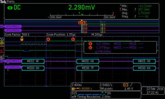
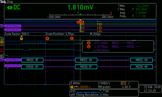
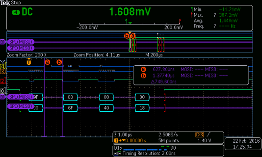
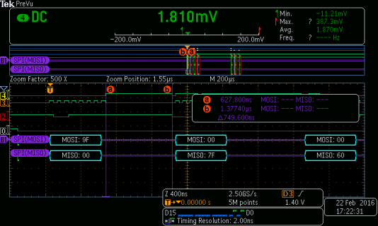
I double-checked all wires are hooked into the correct MISO/MOSI/CS/SCLK, as well as GND & Vcc. I then hooked it up to an oscilloscope, and was able to produce the following scope screenshots:
tek00000.png
tek00001.png
tek00002.png
tek00003.png
Only once out of about 10 times was the scope able to read the correct values for the sequence, which should be: MOSI 94 00 00 00, then MISO 00 EF 40 18. The scope is configured with the following assignments: D0->CS, D2->MOSI, D3->SCLK, D4->MISO.

My best guess is that the memory chip, as soon as it receives the 94 (read ID) command, latches on the value for the first clock cycle for the data return, a 1 for the MSB of EFh (cursor a), and then after about 700-800ns without a clock cycle relaxes to 0 (cursor b). This code was likely developed and run mostly on a Teensy3, which has a higher clock rate, so the intervening 700-800ns between SPI data transfers would be reduced, so this issue likely would not have been seen. Can you confirm or provide possible solutions?

The following are my suggested solutions based on my assessment of the issue:
  • Speed up or reduce the library code that happens between transfers.
  • Manually set the SPI control registers to read on falling edge, the CPOL (either using SPISettings or direct register writes)
  • Make all commands some sort of variant on transfer16, which theoretically would have the clocked bytes transferred without any pause.
 
I think you should try using the standard I2C library to see if you can do this without the library.

SPI_Mode 0 is correct. Reads operate on a rising edge, just like standard I2C

Your first clock pulse on your write seems to be slightly longer on the cases it fails on.
I think we can assume it's the first byte that is incorrect so we should look there
 
Possible SOLUTION found

I think you should try using the standard I2C library to see if you can do this without the library.

SPI_Mode 0 is correct. Reads operate on a rising edge, just like standard I2C

Your first clock pulse on your write seems to be slightly longer on the cases it fails on.
I think we can assume it's the first byte that is incorrect so we should look there

I found a solution/workaround, but I'll get to it in a minute...

I took your suggestion to use the SPI library to read/write raw bites instead of the SerialFlash library, using the following (abbreviated) code:
Code:
#define FLASH_CS_PIN 6
void setup() {
  // put your setup code here, to run once:
  while(!Serial);
  Serial.begin(250000);
  Serial.println("Started");
  uint8_t byte1,byte2,byte3;
  pinMode(FLASH_CS_PIN, OUTPUT);
  digitalWrite(FLASH_CS_PIN, HIGH);
  SPI1.begin();
  //SPI1 for faster clock rate, about 24 MHz vs 12 MHz SPI
  
  for(int i = 0; i<10; i++){
    digitalWrite(FLASH_CS_PIN, LOW);
    SPI1.beginTransaction(SPISettings(50000000, MSBFIRST, SPI_MODE0));
    SPI1.transfer(0x9F);
    byte1=SPI1.transfer(0x00);
    byte2=SPI1.transfer(0x00);
    byte3=SPI1.transfer(0x00);
    SPI1.endTransaction();
    digitalWrite(FLASH_CS_PIN, HIGH);
    Serial.println("Single Transfer Test:");
    Serial.println(byte1, HEX);
    Serial.println(byte2, HEX);
    Serial.println(byte3, HEX);
  }

This didn't work, I ended up with the same problem. The reason for this is that the SerialFlash library uses the same code almost verbatim, calling 4 individual transfer functions to send the command and then retrieve the ID (I don't really care about the ID, but if I can't consistently read the ID correctly then I have no trust in being able to read anything on the chip). I also tried with 16-bit transfers, and that didn't solve the problem, though was slightly faster (code below:)

Code:
uint16_t upper, lower;
  for(int i = 0; i<10; i++){
    digitalWrite(FLASH_CS_PIN, LOW);
    SPI1.beginTransaction(SPISettings(50000000,MSBFIRST, SPI_MODE0));
    upper=SPI1.transfer16(0x9F00);
    lower=SPI1.transfer16(0x0000);
    SPI1.endTransaction();
    digitalWrite(FLASH_CS_PIN, HIGH);
    
    Serial.println("Transfer16 Test:");
    Serial.println(upper, HEX);
    Serial.println(lower, HEX);
    //delay(200);
  }

The problem is not:
  • SPI clock rate.I tried increasing the SPI Clock rate to 24 MHz vs 12 MHz (by using SPI1 instead of SPI), and it didn't seem to make a difference in reading the data.
  • Number of bytes transferred over SPI at a time.

However, I did find a solution to the problem, that appeared to provide perfect reads every time.
By the datasheet of the W25Q128FV (page 11):
Standard SPI instructions use the unidirectional DI (input) pin to serially write instructions, addresses or data to the device on the rising edge of the Serial Clock (CLK) input pin. Standard SPI also uses the unidirectional DO (output) to read data or status from the device on the falling edge of CLK​

So, I decided to try to switch the clock phase in the middle of the transfers, so that the command would clock out over MOSI on the rising edge, but the TeensyLC would read the data/ID on the falling CLK edge. See the following code for demonstration:
Code:
for(int i = 0; i<10; i++){
    digitalWrite(FLASH_CS_PIN, LOW);
    SPI1.beginTransaction(SPISettings(50000000, MSBFIRST, SPI_MODE0));
    SPI1.transfer(0x9F);
    SPI1.endTransaction();
    SPI1.beginTransaction(SPISettings(50000000, MSBFIRST, SPI_MODE1));
    byte1=SPI1.transfer(0x00);
    byte2=SPI1.transfer(0x00);
    byte3=SPI1.transfer(0x00);
    SPI1.endTransaction();
    digitalWrite(FLASH_CS_PIN, HIGH);
    Serial.println("Clock Polarity Test");
    Serial.println(byte1, HEX);
    Serial.println(byte2, HEX);
    Serial.println(byte3, HEX);
  }
This method produced the correct ID every time, which no other method was able to produce. However, the delay in ending and switching transactions is about 2 microseconds, which is extremely long for what should be just flipping a bit in a SPI Control Register. If I need to, I can manage with modifying the SerialFlash library to flip phase between reads and writes, but I would prefer to find the SPI control register and write that directly. Paul (or anyone else very familiar with embedded) Is there any problem with writing the SPI control register between transfers? If I could do that, using a simple inline toggle function, it would drastically cut down the switching time while still providing the read accuracy I can't get any other way.

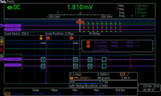
Below is a scope screenshot demonstrating the delay between sending the first command and then switching phase as in the above code. The data passed isn't correct because I was messing around with using SPI_MODE1 for both transactions (and somehow forgot to get a screenshot of the working version), but it does demonstrate the 1.8 us delay. I suppose you'll have to take my word for it until I can get back in the lab tomorrow to prove that it works.
tek00011.png

I guess I will have to work on finding a solution to toggling the clock phase control register, unless anyone else has any suggestions or a better way to do that. To set SPI to read on falling edge, I would just use SPI_C1 |= SPI_C1_CPHA, right? If this works and I get time, I'll try to go through, modify and test SerialFlash with this solution.
 
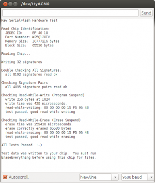
I just ran RawHardwareTest on Teensy-LC with a W25Q128FV. It seems to work fine here. I couldn't reproduce the problem you're seeing.

lc.png
 
Last edited:
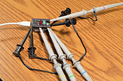
Just to be through, I looked at the waveforms with my scope. Here it is on my desk, so you can see how I tested.

lc.jpg

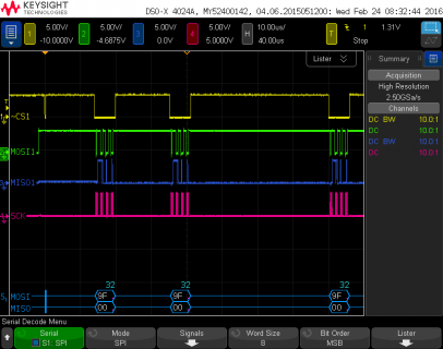
Here's the first 100 us of RawHardwareTest running.

file.png

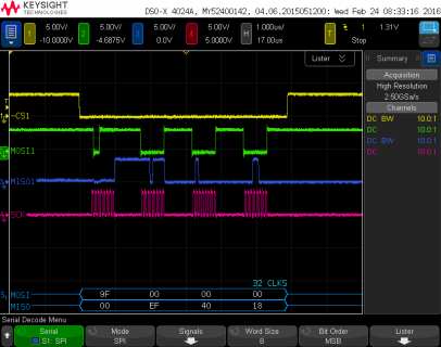
Here's a zoom in to that first SPI transaction where it reads the chip's ID bytes.

file.png
(click for full size)
 
I don't know why it's not working for you.

Honestly, your scope screenshots don't make much sense to me. Looks like a logic analyzer more than a scope... no indication of voltage ranges, no apparent analog noise you'd expect from a normal oscilloscope, and extremely tiny vertical scale.

Anyway, it's absolutely working correctly when I run it here. I'd like to know what the problem is... but at this point all I can say is it's almost certainly something on your end. The library definitely works correctly with this flash chip and Teensy LC.

Hopefully these scope screenshots help?
 
Thanks for your help. I'm working on this for part of a Senior Electrical Engineering project, and can't reasonably move on from this while I still see inconsistencies in reading data.
One possibility is that Winbond updated the silicon on the chip without changing the part number, or that I somehow got a bad lot of chips.

I will keep investigating as I have free time and keep this thread updated.

As to my test hardware, I'm using one of our lab's Tektronix MSO (mixed signal oscilloscope) scopes, which include a sort of logic analyzer capability (the normal scope probes use alligator clips for ground, which was annoying with 4 ground connections to the same point, so I was lazy and switched to the logic analyzer capability because they use a shared ground).

At the very least, it was interesting to see how much overhead there is between the transfer() calls, so I might make a pull request to condense some of those into transfer16() to make a small speed improvement.
 
I think my next step might be hooking up the analog probes and seeing what the falling MISO signal looks like.

Thanks again for your support, and I really appreciate all the fantastic work you've done on the SerialFlash and other Teensy library, it's really made development quick & relatively painless for me & my team!
 
Last edited:
One possibility is that Winbond updated the silicon on the chip without changing the part number,

As you can see in the hardware testing file, I've purchased and tested nearly all of the larger serial NOR flash chips on the market today. Except for 3 cases on small chips, all have passed testing. With Winbond, I've actually purchased the 64 and 128 sizes several times over the last couple years. Never a problem.

Of all the possible explanations for the trouble you're seeing, an unannounced / undocumented change on Winbond's part seems extremely unlikely!

or that I somehow got a bad lot of chips.

If you got them from a shady Aliexpress or Ebay merchant, perhaps you should order some chips from Digikey?
 
As you can see in the hardware testing file, I've purchased and tested nearly all of the larger serial NOR flash chips on the market today. Except for 3 cases on small chips, all have passed testing. With Winbond, I've actually purchased the 64 and 128 sizes several times over the last couple years. Never a problem.

Of all the possible explanations for the trouble you're seeing, an unannounced / undocumented change on Winbond's part seems extremely unlikely!


If you got them from a shady Aliexpress or Ebay merchant, perhaps you should order some chips from Digikey?

No, the chips were sourced from Digikey. If you have any other possible causes or suggestions for this error that I'm seeing, it would be greatly appreciated. I tested this on two separate W25Q128 chips, and had the same problem on each.
 
The chips I tested also came from Digikey.

I do not know why it's not working for you, but my guess would be something not wired up properly. I know you said "double-checked all wires are hooked into the correct MISO/MOSI/CS/SCLK, as well as GND & Vcc", but perhaps there's actually a simple wiring mistake somewhere?
 
LC SPI works for the common man too. I hooked a Winbond W25Q80BV chip to my LC's SPI. The erase example and the rawhardware test ran just fine. I was using IDE 1.6.7 with 1.27 and the latest version of SerialFlash from github. works for me ;)

EDIT: conncected LC to Winbond W25Q64FV(prop shield), erase/rawhardware test and file tests ran just fine at 48MHz and optimized 48mhz
 
Last edited:
Status
Not open for further replies.
Back
Top