
You are using an out of date browser. It may not display this or other websites correctly.
You should upgrade or use an alternative browser.
You should upgrade or use an alternative browser.
Prop Shield Beta Test
- Thread starter Paul
- Start date
- Status
- Not open for further replies.
Ben
Well-known member
Ok, I very carefully tried to follow your thoughts. While there definitely is a bug, your audio comment confuses me quite a but, even with the text overlay.
Anyway, what I think is important to notice is that roll and yaw are visualized correctly all the time. The only thing that's behaving wrong is the visual response to any pitch != 0 if (yaw !=0 || yaw != PI).
My wild guess, by looking sharply at what's happening in the vid, is there is a factor sin(yaw) mixed in the roll that shouldn't be there. Because the bug doesn't show at 0 and Pi and is strongest at Pi/2 -> sin(x).
Edit: Ok scrap what I said, I looked at the function descriptions of the rotateX(), rotateY() and rotateZ() functions. I think the behavior of these functions is by design and they are just not intended to be used the way the are in the sketch:
(Source: https://processing.org/reference/rotateZ_.html)
We need to do some math with the data before it can be plugged into the rotate-functions. I'm sorry I don't have more time on my hands right now to look into this
Anyway, what I think is important to notice is that roll and yaw are visualized correctly all the time. The only thing that's behaving wrong is the visual response to any pitch != 0 if (yaw !=0 || yaw != PI).
My wild guess, by looking sharply at what's happening in the vid, is there is a factor sin(yaw) mixed in the roll that shouldn't be there. Because the bug doesn't show at 0 and Pi and is strongest at Pi/2 -> sin(x).
Edit: Ok scrap what I said, I looked at the function descriptions of the rotateX(), rotateY() and rotateZ() functions. I think the behavior of these functions is by design and they are just not intended to be used the way the are in the sketch:
Code:
Coordinates are always rotated around their relative position to the origin.We need to do some math with the data before it can be plugged into the rotate-functions. I'm sorry I don't have more time on my hands right now to look into this
Last edited:
Based on the below information, may be able to fix the visualization by simply inverting the order of the rotation operations:
https://en.wikipedia.org/wiki/Euler_angles
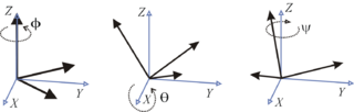
Intrinsic rotations
Intrinsic rotations are elemental rotations that occur about the axes of the rotating coordinate system XYZ, which changes its orientation after each elemental rotation.
Extrinsic rotations
Extrinsic rotations are elemental rotations that occur about the axes of the fixed coordinate system xyz.
Conversion between intrinsic and extrinsic rotations
Any extrinsic rotation is equivalent to an intrinsic rotation by the same angles but with inverted order of elemental rotations, and vice versa.
A rotation represented by Euler angles (α, β, γ) = (−60°, 30°, 45°), using z-x’-z″ intrinsic rotations:
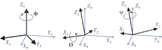
The same rotation represented by (γ, β, α) = (45°, 30°, −60°), using z-x-z extrinsic rotations
https://en.wikipedia.org/wiki/Euler_angles
Intrinsic rotations
Intrinsic rotations are elemental rotations that occur about the axes of the rotating coordinate system XYZ, which changes its orientation after each elemental rotation.
Extrinsic rotations
Extrinsic rotations are elemental rotations that occur about the axes of the fixed coordinate system xyz.
Conversion between intrinsic and extrinsic rotations
Any extrinsic rotation is equivalent to an intrinsic rotation by the same angles but with inverted order of elemental rotations, and vice versa.
A rotation represented by Euler angles (α, β, γ) = (−60°, 30°, 45°), using z-x’-z″ intrinsic rotations:
The same rotation represented by (γ, β, α) = (45°, 30°, −60°), using z-x-z extrinsic rotations
Last edited:
IMO, the sequence of rotation is not correct
with
I get what I consider correct rotations
As I have no poti etc
I run the following program in processing
with
Code:
  rotateY(-yaw); // yaw
  rotateX(pitch); // RotateX pitch value
rotateZ(-roll); // rollAs I have no poti etc
I run the following program in processing
Code:
float yaw;
float pitch;
float roll;

void setup()
{
  size(600, 500, P3D);

  textSize(16); // set text size
  textMode(SHAPE); // set text mode to shape

  pitch=0.0;
  roll=0.0;
  yaw=1.0;

}

void draw()
{
  pitch = pitch +0.01;
  yaw = yaw+0.0;
  roll = roll +0.0;

  background(255); // set background to white

  translate(width/2, height/2); // set position to centre

  pushMatrix(); // begin object

  rotateY(-yaw); // yaw
  rotateX(pitch); // RotateX pitch value
  rotateZ(-roll); // roll

  drawArduino(); // function to draw rough Arduino shape

  popMatrix(); // end of object

  // Print values to console
  print(pitch);
  print("\t");
  print(roll);
  print("\t");
  print(-yaw);
  println("\t");

}

void drawArduino() {
  /* function contains shape(s) that are rotated with the IMU */
  stroke(0, 90, 90); // set outline colour to darker teal
  fill(0, 130, 130); // set fill colour to lighter teal
  box(300, 10, 200); // draw Arduino board base shape

  stroke(0); // set outline colour to black
  fill(80); // set fill colour to dark grey

  translate(60, -10, 90); // set position to edge of Arduino box
  box(170, 20, 10); // draw pin header as box

  translate(-20, 0, -180); // set position to other edge of Arduino box
  box(210, 20, 10); // draw other pin header as box
}
Last edited:
sumotoy
Well-known member
Ouch! You right, sorry you loose all this time around. The arduino visualizer it's simply wrong.After much frustration with wrong results in Arduino's orientation visualizer example, I finally arrived at this conclusion:
Late in 2012, the old friend Fabio (missed him a lot...) wroted something like the attachment.
It has modified to accomodate Processing 3 but of course it expect a different serial format so actually needs to be modified for run with prop-shield.
He choosed to start a 3d visualization from a fixed angle, then have to align the IMU board to that angle and press a button...
Dunno if this is a correct way to go, I was sure that compass it's enough to give a start point for the 3D rotation but I don't know really processing enough...
Attachments
Well, no so much.The arduino visualizer it's simply wrong.
there are only three rotations.
As I said and as you may observe from the animation in JBeale's post, the sequence of rotations are
- yaw
- pitch
- roll
and not
- pitch
- raw
- roll
Note: if you wanted to undo the rotations, you must start with roll, followed by pitch and in the end with yaw
What I do not like is the choice of axes (i.e. roll around z axis), and I will continue to use x- forward, y to the left and z upward, i.e yaw (heading) rotation around z, pitch: rotation around y; ans roll rotation around x axis). But if you have to be compatible to say aircraft notation, so it be.
PaulStoffregen
Well-known member
maybe Kris will update his bakeoff with the prop shield sensors ....
Probably best to do so *after* the final calibration software is published.
I'm seriously considering adding cal of the accelerometer and gyro offsets to the cal app. Anyone have opinions or feedback about that?
Wozzy
Well-known member
Pitch/Roll error when Yawed
I'm not sure that the Pitch/Roll with Yaw problem lies with the Curie visualizer alone.
Last night I was Stripcharting the Heading, Pitch, & Roll outputs from both the NXP_Sensor_Fusion and Mahony AHRS algorithms.
It seems that the issue is also present there as well.
I'll see if I can perform more testing and make a video tonight when I can get back to my play bench.
Last edited:
Wozzy
Well-known member
I'm seriously considering adding cal of the accelerometer and gyro offsets to the cal app. Anyone have opinions or feedback about that?
Offsets can be accomplished with a ZERO button or a software button in a gui.
I guess in the simplest case, a timer could be used to give the user a set time to position and steady the IMU before the tare data is acquired.
Changing the sensitivities would likely be beyond the capability of the average user as precision fixtures and alignment would be required.
Last edited:
Probably best to do so *after* the final calibration software is published.
I'm seriously considering adding cal of the accelerometer and gyro offsets to the cal app. Anyone have opinions or feedback about that?
While accelerometer calibration can be done with earth gravity, for gyro we would need some spinning device.
Some people I know use old-fashioned disk player to get 2 or 3 well defined rotation rates.
So, maybe someone with more mechanical skills develops a cost-effective gyro calibration sketch (teensy controlled rotating plate) to be used for gyro calibration.
manitou
Senior Member+
another standalone processing visualization tester using key presses for yaw, pitch, and roll. rotation ordered per post #306
Code:
// tty3d   y p r 1 9 0 + -
float sign=1.0, delta=0.1;
float yaw;
float pitch;
float roll;
String message;
String [] ypr = new String [3];

void setup()
{
  size(600, 500, P3D);

  textSize(16); // set text size
  textMode(SHAPE); // set text mode to shape
}

void draw()
{
  background(255); // set background to white
  lights();

  translate(width/2, height/2); // set position to centre

  pushMatrix(); // begin object

  rotateY(-yaw); // yaw
  rotateX(pitch); // RotateX pitch value
  rotateZ(-roll); // roll

  drawArduino(); // function to draw rough Arduino shape

  popMatrix(); // end of object


}

void keyPressed()
{
  if(key == 'y') yaw += sign*delta;
  if(key == 'p') pitch += sign*delta;
  if(key == 'r') roll += sign*delta;
  if(key == '+') sign = 1.0;
  if(key == '-') sign = -1.0;
  if(key == '1') delta = 0.1;
  if(key == '9') delta = 3.14159/4.;  // 45 degrees
  if(key == '0') roll=yaw=pitch= 0.0;
  // Print values to console
  print(pitch);
  print("\t");
  print(roll);
  print("\t");
  print(yaw);
  println("\t");
}
void drawArduino() {
  /* function contains shape(s) that are rotated with the IMU */
  stroke(0, 90, 90); // set outline colour to darker teal
  fill(0, 130, 130); // set fill colour to lighter teal
  box(300, 10, 200); // draw Arduino board base shape

  stroke(0); // set outline colour to black
  fill(80); // set fill colour to dark grey

  translate(60, -10, 90); // set position to edge of Arduino box
  box(170, 20, 10); // draw pin header as box

  translate(-20, 0, -180); // set position to other edge of Arduino box
  box(210, 20, 10); // draw other pin header as box
}
Last edited:
Ben
Well-known member
I'd like to propose a UI detail: Don't tell the user to hold the board still for "n" seconds, instead tell the user to put the board on an even surface and then use the variance of the incoming data do determine if the prop shield is held "still enough". Don't use data if variance is too high, use it and signal the user to do whatever comes next if variance is low enough.I'm seriously considering adding cal of the accelerometer and gyro offsets to the cal app. Anyone have opinions or feedback about that?
Edit:
I made a 3D model of the Prop Shield to replace drawArduino() function in processing 3 by drawPropShield().
@Paul: Is it ok to post the source code or does this fall under the "no pictures" rule? The model shows the approximate size and position of all major components as well as the plated through-holes.
Last edited:
PaulStoffregen
Well-known member
instead tell the user to put the board on an even surface and then use the variance of the incoming data do determine if the prop shield is held "still enough".
Yes, this is basically what I was thinking, looking at the changes in acceleration and for low values from the gyro.
PaulStoffregen
Well-known member
Looks like the visualizers *and* Madgwick filter are using the same external frame Euler angle references.
If you run Madgwick and just watch the data, you can see spinning Teensy + Prop Shield on axis of the USB cable gives roll when the board is oriented one way, but it give pitch when you change the heading/yaw orientation by 90 degrees.
Somehow, I expect an IMU to give roll, pitch and yaw readings like you'd expect from inside an airplane. When the nose of the plane starts pointing downward, that's minus pitch, regardless of whether you're flying from Seattle to LA or NYC. Madgick reports it as pitch if you're flying towards Los Angles, but consides it roll when you're heading towards New York, or some of both if you're flying to Miami.
NXPSensorFusion (Freescale's algorithm) gives roll, pitch & yaw as you'd experience from the aircraft's (intrinsic) perspective.
I managed to change the visualizer to use intrinsic roll, pitch, yaw. Here's the code:
Code:
import processing.serial.*;
Serial myPort;

int newLine = 13; // new line character in ASCII
float yaw;
float pitch;
float roll;
String message;
String [] ypr = new String [3];

void setup()
{
  size(600, 500, P3D);
  lights();

  /*Set my serial port to same as Arduino, baud rate 9600*/
  //myPort = new Serial(this, Serial.list()[0], 9600); // if you have only ONE COM port active
  myPort = new Serial(this, "/dev/ttyACM0", 9600);  // if you know the 101 COM port

  textSize(16); // set text size
  textMode(SHAPE); // set text mode to shape
}

void draw()
{
  serialEvent();  // read and parse incoming serial message
  background(255); // set background to white

  translate(width/2, height/2); // set position to centre

  pushMatrix(); // begin object

  float c1 = cos(-roll);
  float s1 = sin(-roll);
  float c2 = cos(pitch);
  float s2 = sin(pitch);
  float c3 = cos(-yaw);
  float s3 = sin(-yaw);
  applyMatrix( c2*c3, s1*s3+c1*c3*s2, c3*s1*s2-c1*s3, 0,
               -s2, c1*c2, c2*s1, 0,
               c2*s3, c1*s2*s3-c3*s1, c1*c3+s1*s2*s3, 0,
               0, 0, 0, 1);

  drawArduino(); // function to draw rough Arduino shape

  popMatrix(); // end of object

  // Print values to console

  print(roll);
  print("\t");
  print(pitch);
  print("\t");
  print(-yaw);
  println();

  myPort.write("s"); // write an "s" to receive more data from Arduino
}

void serialEvent()
{
  message = myPort.readStringUntil(newLine); // read from port until new line (ASCII code 13)
  if (message != null) {
    ypr = split(message, ","); // split message by commas and store in String array
    yaw = float(ypr[0]); // convert to float yaw
    pitch = float(ypr[1]); // convert to float pitch
    roll = float(ypr[2]); // convert to float roll
  }
}
void drawArduino() {
  /* function contains shape(s) that are rotated with the IMU */
  stroke(0, 90, 90); // set outline colour to darker teal
  fill(0, 130, 130); // set fill colour to lighter teal
  box(300, 10, 200); // draw Arduino board base shape

  stroke(0); // set outline colour to black
  fill(80); // set fill colour to dark grey

  translate(60, -10, 90); // set position to edge of Arduino box
  box(170, 20, 10); // draw pin header as box

  translate(-20, 0, -180); // set position to other edge of Arduino box
  box(210, 20, 10); // draw other pin header as box
}PaulStoffregen
Well-known member
Is it ok to post the source code or does this fall under the "no pictures" rule?
A model is fine.
Ben
Well-known member
You can use this drawPropShield() function instead of drawArduino(). I don't know whether I got the orientation right, propably not, but that should be fixed easily by cyclically exchanging the function parameters.
Edit: Screenshot:

Code:
int fpsMillis = 0;
int fps = 0;

void setup()
{
  size(600, 500, P3D);
  textSize(16); // set text size
  textMode(SHAPE); // set text mode to shape
  sphereDetail(15);
}

void draw()
{
  background(255); // set background to white

  if (millis() - fpsMillis > 500) {
    fpsMillis = millis();
    fps = (int)frameRate;
  }
  fill(0);
  text(fps + " fps",10,20);

  translate(width/2, height/2, 200); // set position to centre
  pushMatrix(); // begin object
  rotateX( sin(millis()/700.f)/1.6 - 3.1415f/4 );
  rotateY( sin(millis()/2000.f)/2);
  drawPropShield();
  popMatrix(); // end of object
}

void drawPropShield() {

  stroke(0); // black outline
  fill(0, 128, 0); // fill color PCB green
  box(190, 6, 70); // PCB base shape

  fill(255, 215, 0); // gold color
  noStroke();

  //draw 14 contacts on Y- side
  translate(65, 0, 30);
  for (int i=0; i<14; i++) {
    sphere(4.5); // draw gold contacts
    translate(-10, 0, 0); // set new position
  }

  //draw 14 contacts on Y+ side
  translate(10, 0, -60);
  for (int i=0; i<14; i++) {
    sphere(4.5); // draw gold contacts
    translate(10, 0, 0); // set position
  }

  //draw 5 contacts on X+ side (DAC, 3v3, gnd)
  translate(-10,0,10);
  for (int i=0; i<5; i++) {
    sphere(4.5);
    translate(0,0,10);
  }

  //draw 4 contacts on X+ side (G C D 5)
  translate(25,0,-15);
  for (int i=0; i<4; i++) {
    sphere(4.5);
    translate(0,0,-10);
  }

  //draw 4 contacts on X- side (5V - + GND)
  translate(-180,0,10);
  for (int i=0; i<4; i++) {
    sphere(4.5);
    translate(0,0,10);
  }

  //draw audio amp IC
  stroke(128);
  fill(24);    //Epoxy color
  translate(30,-6,-25);
  box(13,6,13);

  //draw pressure sensor IC
  stroke(64);
  translate(32,0,0);
  fill(192);
  box(10,6,18);

  //draw gyroscope IC
  stroke(128);
  translate(27,0,0);
  fill(24);
  box(16,6,16);

  //draw flash memory IC
  translate(40,0,-15);
  box(20,6,20);

  //draw accelerometer/magnetometer IC
  translate(-5,0,25);
  box(12,6,12);

  //draw 5V level shifter ICs
  translate(42.5,2,0);
  box(6,4,8);
  translate(0,0,-20);
  box(6,4,8);
}
Edit: Screenshot:
Last edited:
manitou
Senior Member+
I managed to change the visualizer to use intrinsic roll, pitch, yaw.
FWIW, lights() needs to be in draw() to remain persistent.
defragster
Senior Member+
Looks like the visualizers *and* Madgwick filter are using the same external frame Euler angle references.
If you run Madgwick and just watch the data, you can see spinning Teensy + Prop Shield on axis of the USB cable gives roll when the board is oriented one way, but it give pitch when you change the heading/yaw orientation by 90 degrees.
It this related to Gimbal Lock like here Gimbal Lock – Rotation order while Animating a Character
> At 2 minutes building to 2:20+ it shows the character having spastic axis rotation - fixed there by changing the order of axis evaluation. This seems to be what WMXZ was alluding to in his post #306
... reports it as pitch if you're flying towards Los Angles, but consides it roll when you're heading towards New York, or some of both if you're flying to Miami.
If a plane from Boston to Seattle diverts to Dallas and suffers a horizon shift . . . which way are the survivors facing?
PaulStoffregen
Well-known member
I've updated NXPMotionSense and MahonyAHRS. Madgick still needs work, but the Massimo gave me access to it... so fixes coming soon.
https://github.com/PaulStoffregen/NXPMotionSense
https://github.com/PaulStoffregen/MahonyAHRS
I put an updated copy of the visualizer with Ben's awesome rendering of the prop shield and proper intrinsic rotations here:
https://github.com/PaulStoffregen/N...ientationVisualiser/OrientationVisualiser.pde
The protocol has changed from Arduino's Curie example to Adafruit's BNO055 bunny example.
The Orientation and Mahony examples have been updated. Things seem to be working much better now that it's all intrinsic rotation, as you'd expect for roll, pitch & yaw!
(edit: and yes, I know there's redundant math in the Mahony functions.... will make it more efficient tomorrow)
- Status
- Not open for further replies.