Rs485 halfduplex for Dynamixel with Teensy 3.1 without external Buffer chip

Elmue

Well-known member
Hello

Once again I have added a new feature to Teensy.
Once again I send code that is working and proved.
Once again I hope that Paul will add this functionality to the Teensy core.


Many people out there want to control a Dynamixel servo with a Teensy.
Dynamixel servos are very powerful and precise.
You will not find any other servo with that precision for that price.

The Teensy 3.1 has a much more powerful processor than many Arduino boards.
It is so fast that it has no problem to drive the Dynamixel at 1 mega baud (which is the factory default).

But if you search on Google how to drive a Dynamixel you find some posts on PJRC.com and on Trossenrobotics.com
but NOT EVEN ONE forum discussion offers a working code to set the Teensy into tristate mode.

It is the opposite: You find misleading postings where people use an external 74HC241 chip to make the Teensy 3-state.
But this is nonsense.
You do NOT need any external chips!
You can connect the Dynamixel directly to the Teensy.

The Dynamixel AX 12 uses RS485 at TTL level which means that it's signals are between 0 V and 5 V.
The Teensy 3.1 sends signals between 0 V and 3.3 V.
But this is no problem: The comunication works perfectly.

The CPU of the Teensy 3.1 offers the functionality to switch the TX pin of the UART into Tristate mode.
The CPU is able to drive a RS485 half-duplex bus without any external chips.

But how do I do this in a Sketch ?
This important funcionality is missing in the Teensy core library.
And if you search in internet which CPU registers must be manipulated to make the TX pin tristate, you will waste hours without success.

For that reason I post an approved solution here that I tested on Teensy 3.1 with a Dynamixel AX12 servo running at 1 Mega Baud.
_______________________________________________

Here come 3 functions that switch the TX pins of Serial1, Serial2 and Serial3 between tristate mode and normal mode:

Code:
void serial1_enable_TX_tristate(bool bEnable)
{
    if (bEnable) CORE_PIN1_CONFIG = PORT_PCR_DSE | PORT_PCR_ODE | PORT_PCR_MUX(3); // set Open Drain Enabled
    else         CORE_PIN1_CONFIG = PORT_PCR_DSE | PORT_PCR_SRE | PORT_PCR_MUX(3); // set Slew Rate Enabled
}

void serial2_enable_TX_tristate(bool bEnable)
{
    if (bEnable) CORE_PIN10_CONFIG = PORT_PCR_DSE | PORT_PCR_ODE | PORT_PCR_MUX(3); // set Open Drain Enabled
    else         CORE_PIN10_CONFIG = PORT_PCR_DSE | PORT_PCR_SRE | PORT_PCR_MUX(3); // set Slew Rate Enabled
}

void serial3_enable_TX_tristate(bool bEnable)
{
    if (bEnable) CORE_PIN8_CONFIG = PORT_PCR_DSE | PORT_PCR_ODE | PORT_PCR_MUX(3); // set Open Drain Enabled
    else         CORE_PIN8_CONFIG = PORT_PCR_DSE | PORT_PCR_SRE | PORT_PCR_MUX(3); // set Slew Rate Enabled
}

In tristate mode the pull-up resistor in the CPU is enabled.
In normal mode the CPU pulls the pin directly to GND and +3.3 V.

I tested these functions on Teensy 3.1 but I suppose they will also work on the other Teensy boards.

I hope that Paul will add these 3 functions to the core library and add the corresponding functions in HardwareSerial.h.

________________________________________________

And here come 2 more functions that you write into your sketch:

Code:
// Open Serial1 at 1 mega baud and in tristate mode
void Dynamixel_Serial1_Open()
{
    Serial1.begin(1000000, SERIAL_8N1);
	
    serial1_enable_TX_tristate(true);
}

// Send the instruction packet to the Dynamixel servo and then switch the TX pin back to tristate
void Dynamixel_Serial1_Write(byte* data, int count)
{
    serial1_enable_TX_tristate(false);            

    for (int i=0; i<count; i++)
    { 
        Serial1.write(data[i]);
    }

    Serial1.flush(); // waits until the last data byte has been sent
    serial1_enable_TX_tristate(true);            
}

Isn't that super easy ?

IMPORTANT:
While sending data the TX pin is NOT anymore in tristate mode.
The CPU sends data in normal mode (pin switched to digital output) and pulls the data line ACTIVELY up and down.
This is required to allow high speed like 1 mega baud.

The internal pull up is only in use while the Teensy is waiting for a servo response.

____________________________________________

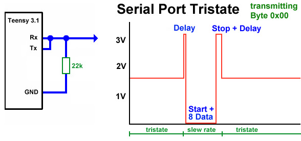
How do you check that tristate is working correctly ?
Obvioulsy you need an oscilloscope to check that.

Then you connect a 22k resistor from Tx to ground.
The internal pull up resistor in the CPU is also 22k Ohm.
So in tristate mode the TX pin will be at approx 3.3V / 2 = 1.7 V.

With this code:

Code:
void loop()
{
    byte data[] = { 0x00 };
    Dynamixel_Serial1_Write(data, 1);
    delay(1);
}

you will see on the oscilloscope:

Tristate Rs485.png

As you see there is a short delay between switching to normal mode and the Start bit
and another delay between the stop bit and switching back to tristate mode.
This delay is about 2 µs on Teensy 3.1 running at a CPU clock of 96 MHz.
During this delay the TX line is HIGH.
__________________________________________

And how do you connect the Dynamixel ?

The Dynamixel should be connected via a 100 Ohm resistor as a protection.
In case that both (Teensy and Dynamixel) send at the same time it protects the output pins.
But this will only happen if there is something wrong in your sketch.
Normally it will never happen that both send at the same time.

Apart from that normally the CPU pins survive shortcuts for a short time.
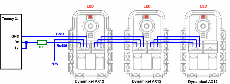
DynamixelWithTeensy.png
________________________________________

What can you do if it does not work ?

1.) When you power up the AX12 servo the red LED at the bottom side must flash up once for one second.
If it does not, check the 12 V supply.

2.) The factory default of Dynamixel is 1 mega baud.
If you have changed the baudrate of the servo and forgot it, then you have a problem.
You will have to try all possible baud rates.

3.) The factory default is servo ID = 1.
If you have changed the servo ID and forgot it, that's no problem:
Send a PING packet to the broadcast ID and the servo will respond with it's ID.
Obviously you must connect only ONE servo at the same time.

4.) Check the signal with an oscilloscope.

5.) If you have doubts that the failure might be caused by a lack of your electronic / sketch programming skills,
the bullet proof solution is to buy a USB2Dynamixel adapter and connect the servo directly to the PC.
This allows to test the servo without Teensy.

________________________________________

Delays

After sending an instruction packet to the servo you will normally immediately read the returned Status packt.
With the servo register "Return Delay Time" you can define the delay before the servo responds with it's status packet.
The Teensy takes only approx 2 µs to switch back to tristate.
Nevertheless I recommend to do your first tests with the register "Return Delay Time" at it's maximum value.
Later, when all works correctly, you can fine tune this register (if you really need so much speed).

________________________________________

Echoed data

As the Tx and Rx pins are tied together you will first receive an echo of the instruction packet that you have sent.
Behind that echo you will receive the response from the servo.
This is very useful because you can prove in your code that all sent bytes are echoed correctly.
If they are not, this is a severe error.
This allows to detect for example a shortcut of the RS485 data line to ground.

The Teensy uses a FIFO RX buffer of default = 64 byte for Serial1, Serial2 and Serial3.
You can change these defaults in the files serial1.c, serial2.c and serial3.c

Normally the Status packet is very short and the RX buffer is big enough to receive it entirely.
But if you read ALL servo registers at once with the instruction READ DATA, the RX data will be = (Echo + Status + All servo registers) which may be longer than 64 bytes.
If you run at 1 mega baud and do not start immediately to read the response you may lose data.
You can either increase the RX buffer size or not read all registers at once.

________________________________________

Here I post a sketch that works immediately on Teensy 3.1/3.2 and AX12.
It flashes the LED at the bottom side of the servo.
Please note that the code is incomplete.
It is just a demo that communicates with the servo.
To complete the code you must read the servo response in loop().
To check that 3-state is working correctly use an oscilloscope.

Code:
// Test sketch for Dynamixel AX12
// The Rx and Tx pins at the Teensy must be tied together and connected via 100 Ohm to the Dynamixel data line!

// TODO: read status packet returned from servo
// TODO: check the checksum
// ATTENTION: Reading the servo response must be done in loop() NOT in SendInstruction() !!


// Factory default of Dynamixel servos is ID=1, Baudrate= 1 MegaBaud
#define SERVO_ID  1
#define BAUDRATE  1000000

// For debugging in Serial Monitor
#define DEBUGOUT Serial

// The Dynamixel instructions
enum eInstruction
{
    I_Ping      = 1,
    I_ReadData  = 2,
    I_WriteData = 3,
    I_RegWrite  = 4,
    I_Action    = 5,
    I_Reset     = 6,
    I_SyncWrite = 0x83,
};

// The Dynamixel registers
enum eRegister
{
    // ---------- EEPROM ------------

    R_ModelNumber             = 0x00, // 2 Byte
    R_FirmwareVersion         = 0x02, // 
    R_ServoID                 = 0x03, //         Write
    R_BaudRate                = 0x04, //         Write
    R_ReturnDelayTime         = 0x05, //         Write
    R_CW_AngleLimit           = 0x06, // 2 Byte  Write
    R_CCW_AngleLimit          = 0x08, // 2 Byte  Write
    R_HighestLimitTemperature = 0x0B, //         Write
    R_LowestLimitVoltage      = 0x0C, //         Write
    R_HighestLimitVoltage     = 0x0D, //         Write
    R_MaxTorque               = 0x0E, // 2 Byte  Write
    R_StatusReturnLevel       = 0x10, //         Write
    R_AlarmLED                = 0x11, //         Write
    R_AlarmShutdown           = 0x12, //         Write
    R_DownCalibration         = 0x14, // 2 Byte
    R_UpCalibration           = 0x16, // 2 Byte

    // ----------- RAM -------------

    R_TorqueEnable            = 0x18, //         Write
    R_LED                     = 0x19, //         Write
    R_CW_ComplianceMargin     = 0x1A, //         Write
    R_CCW_ComplianceMargin    = 0x1B, //         Write
    R_CW_ComplianceSlope      = 0x1C, //         Write
    R_CCW_ComplianceSlope     = 0x1D, //         Write
    R_GoalPosition            = 0x1E, // 2 Byte  Write
    R_MovingSpeed             = 0x20, // 2 Byte  Write
    R_TorqueLimit             = 0x22, // 2 Byte  Write
    R_PresentPosition         = 0x24, // 2 Byte
    R_PresentSpeed            = 0x26, // 2 Byte
    R_PresentLoad             = 0x28, // 2 Byte
    R_PresentVoltage          = 0x2A, //
    R_PresentTemperature      = 0x2B, //
    R_RegisteredInstruction   = 0x2C, //         Write
    R_Moving                  = 0x2E, //
    R_Lock                    = 0x2F, //         Write
    R_Punch                   = 0x30, // 2 Byte  Write
};

// Dynamixel errors returned in Status packet
enum eError
{
    E_InputVoltage   = 0x01,
    E_AngleLimit     = 0x02,
    E_Overheating    = 0x04,
    E_ParameterRange = 0x08,
    E_Checksum       = 0x10,
    E_Overload       = 0x20,
    E_Instruction    = 0x40,
};


// Global variables
bool gb_LED = false;

void setup(void) 
{
    Serial1.begin(BAUDRATE, SERIAL_8O1);
    Serial1EnableOpenDrain(true);
    pinMode(LED_BUILTIN, OUTPUT);

    DEBUGOUT.begin(115200);
}

void loop(void) 
{
    gb_LED = !gb_LED;
    SetServoLED(gb_LED);
    digitalWrite(LED_BUILTIN, gb_LED ? HIGH : LOW);
    delay(1000);
}

// Turns the LED at the bottom side of the servo on or off
bool SetServoLED(bool b_On)
{
    byte u8_Data[2];
    u8_Data[0] = R_LED;
    u8_Data[1] = b_On ? 1 : 0;
    return SendInstruction(SERVO_ID, I_WriteData, u8_Data, sizeof(u8_Data));
}

bool SendInstruction(byte u8_ServoID, byte u8_Instruction, byte* u8_Params, int s32_ParamCount)
{
    byte u8_TxPacket[100];

    // -------- SEND INSTRUCTION ------------
    
    int S=0;
    u8_TxPacket[S++] = 0xFF;
    u8_TxPacket[S++] = 0xFF;
    u8_TxPacket[S++] = u8_ServoID;
    u8_TxPacket[S++] = s32_ParamCount + 2;
    u8_TxPacket[S++] = u8_Instruction;
    
    for (int i=0; i<s32_ParamCount; i++)
    {
        u8_TxPacket[S++] = u8_Params[i];
    }

    byte u8_Checksum = 0;
    for (int i=2; i<S; i++)
    {
        u8_Checksum += u8_TxPacket[i];
    }
    u8_TxPacket[S++] = ~u8_Checksum;

    PrintHex("Instruction: ", u8_TxPacket, S);
    Serial1.clear();

    Serial1EnableOpenDrain(false);
    Serial1.write(u8_TxPacket, S);
    Serial1.flush(); // waits until the last data byte has been sent
    Serial1EnableOpenDrain(true);
    
    // -------- READ ECHO (timeout = 1 second) ------------

    uint32_t u32_Start = millis();
    int R=0;
    while (R<S)
    {  
        if ((millis() - u32_Start) > 1000)
        {
            DEBUGOUT.println("ERROR: Timeout waiting for Echo (Rx and Tx must be tied togteher)");
            return false;
        }
        
        if (!Serial1.available())
            continue;
        
        if (Serial1.read() != u8_TxPacket[R++])
        {
             DEBUGOUT.println("ERROR: Invalid echo received");
             return false;
        }
    }

    DEBUGOUT.println("Valid echo received.");    

    // ATTENTION: You can NOT read the servo response HERE. You must return from loop() to receive more RX data!

    return true;
}

// Toggle Pin1 (Serial 1 TX pin) between Open Drain and Slew Rate.
// ATTENTION: OUTPUT_OPENDRAIN in Teensyduino 1.28 does not work with UART. Do not use it !
void Serial1EnableOpenDrain(bool bEnable)
{
    if (bEnable) CORE_PIN1_CONFIG = PORT_PCR_DSE | PORT_PCR_ODE | PORT_PCR_MUX(3); // set Open Drain Enabled
    else         CORE_PIN1_CONFIG = PORT_PCR_DSE | PORT_PCR_SRE | PORT_PCR_MUX(3); // set Slew Rate Enabled
}

void PrintHex(const char* s8_Text, const byte* data, int count)
{
    DEBUGOUT.print(s8_Text);
    
    for (int i=0; i < count; i++)
    {
        if (i > 0)
            DEBUGOUT.print(" ");
        
        if (data[i] <= 0xF)
            DEBUGOUT.print("0");
          
        DEBUGOUT.print(data[i], HEX);
    }
    DEBUGOUT.println();
}

Elmü
 
Last edited:
Maybe like this?

Code:
void serial_set_tx(uint8_t pin, uint8_t opendrain)
{
        uint32_t cfg;

        if (opendrain) pin |= 128;
        if (pin == tx_pin_num) return;
        if ((SIM_SCGC4 & SIM_SCGC4_UART0)) {
                switch (tx_pin_num & 127) {
                        case 1:  CORE_PIN1_CONFIG = 0; break; // PTB17
                        case 5:  CORE_PIN5_CONFIG = 0; break; // PTD7
                        #if defined(KINETISL)
                        case 4:  CORE_PIN4_CONFIG = 0; break; // PTA2
                        #endif
                }
                if (opendrain) {
                        cfg = PORT_PCR_DSE | PORT_PCR_ODE;
                } else {
                        cfg = PORT_PCR_DSE | PORT_PCR_SRE;
                }
                switch (pin & 127) {
                        case 1:  CORE_PIN1_CONFIG = cfg | PORT_PCR_MUX(3); break;
                        case 5:  CORE_PIN5_CONFIG = cfg | PORT_PCR_MUX(3); break;
                        #if defined(KINETISL)
                        case 4:  CORE_PIN4_CONFIG = cfg | PORT_PCR_MUX(2); break;
                        #endif
                }
        }
        tx_pin_num = pin;
}

And this in the C++ API:

Code:
        virtual void setTX(uint8_t pin, bool opendrain=false) { serial_set_tx(pin, opendrain); }

1.28 adds setTX() and setRX() to allow people to configure which pins to use, so this feature needs to integrate with the user-configurable pins.
 
Last edited:
Yes, this is a possible solution.

Supposed a user wants to use the default pin of for example Serial1 and switch it tristate, he would have to know which pin to pass as the first parameter.

So my proposal is that it is possible to pass -1 for the first parameter to chose the default pin.


If the user sends data on the default pin with this code he would have to

- setTX(-1, false)
- send data
- flush
- setTX(-1, true)

Obviously the delay would be longer with your code than with my speed optimized code but I think this would not be a problem.
At least not for Dynamixel which allows to define a response delay time of up to 1 millisecond.

(There is an error in the Dynamixel datasheet: It says:
Return Delay Time. The time it takes for the Status Packet to return after the Instruction
Packet is sent. The delay time is given by 2uSec * Address5 value.

But in reality it is 4µs * Register 5 value
which results in a maximum of 4µs * 255 = 1020 µs.)
____________________________


I don't quite understand your code.
The only possible options for the TX pin are 1, 5, 4 ?

Maybe you return false if the user passes an invalid pin number ?
 
Last edited:
Warning: This has also been discussed up on Trossen Robotics
forums.

Note: I have been doing DXL stuff with Teensy 3.1/2s for awhile now and have my own versions of the Dynamixel library up at: https://github.com/KurtE/BioloidSerial

It has also been pointed out that DXL protocol is a 5v protocol. I have had reasonable luck without level shifters, but others have had issues as they say a high should be at least .7 of the voltage or about 3.5v... Also this is not RS485... It is normal half duplex TTL level signals...


Right now experimenting with different level shifters, including ones with direction IO pin. But before then I would do things like:
Code:
void ax12Init(long baud, Stream* pstream ){
    // Need to enable the PU resistor on the TX pin
    s_paxStream = pstream; 

    // Lets do some init here
    if (s_paxStream == &Serial) {
        Serial.begin(baud);
    }  
  
    if (s_paxStream == (Stream*)&Serial1) {
        Serial1.begin(baud);
#if defined(__MK20DX256__) || defined(__MKL26Z64__)
        UART0_C1 |= UART_C1_LOOPS | UART_C1_RSRC;
        CORE_PIN1_CONFIG = PORT_PCR_DSE | PORT_PCR_SRE | PORT_PCR_MUX(3) | PORT_PCR_PE | PORT_PCR_PS; // pullup on output pin;
#endif
    }    
#ifdef SERIAL_PORT_HARDWARE1
    if (s_paxStream == &Serial2) {
        Serial2.begin(baud);
#if defined(__MK20DX256__)  || defined(__MKL26Z64__)

        UART1_C1 |= UART_C1_LOOPS | UART_C1_RSRC;
        CORE_PIN10_CONFIG = PORT_PCR_DSE | PORT_PCR_SRE | PORT_PCR_MUX(3) | PORT_PCR_PE | PORT_PCR_PS; // pullup on output pin;
#endif
    }    
#endif
#ifdef SERIAL_PORT_HARDWARE2
    if (s_paxStream == &Serial3) {
        Serial3.begin(baud);
#if defined(__MK20DX256__)  || defined(__MKL26Z64__)
        UART2_C1 |= UART_C1_LOOPS | UART_C1_RSRC;
        CORE_PIN8_CONFIG = PORT_PCR_DSE | PORT_PCR_SRE | PORT_PCR_MUX(3) | PORT_PCR_PE | PORT_PCR_PS; // pullup on output pin;
#endif
    }    
#endif
    setRX(0);    
}

To set to TX mode:
Code:
void setTXall(){
#if defined(__MK20DX256__)  || defined(__MKL26Z64__)
#define UART_C3_TXDIR			(uint8_t)0x20			// Transmitter Interrupt or DMA Transfer Enable.
    // Teensy 3.1
    if (s_paxStream == (Stream*)&Serial1) {
        uint8_t c;
        c = UART0_C3;
        c |= UART_C3_TXDIR;
        UART0_C3 = c;
    }
    if (s_paxStream == (Stream*)&Serial2) {
        uint8_t c;
        c = UART1_C3;
        c |= UART_C3_TXDIR;
        UART1_C3 = c;
    }
    if (s_paxStream == (Stream*)&Serial3) {
        uint8_t c;
        c = UART2_C3;
        c |= UART_C3_TXDIR;
        UART2_C3 = c;
... (have stuff for other processor)
    }

Set to RX is similar, except wait until TX has completed...
Code:
void setRX(int id){ 
  
    // First clear our input buffer
	flushAX12InputBuffer();
    s_paxStream->flush();
    // Now setup to enable the RX and disable the TX
#if defined(__MK20DX256__)  || defined(__MKL26Z64__)
#define UART_C3_TXDIR			(uint8_t)0x20			// Transmitter Interrupt or DMA Transfer Enable.
    // Teensy 3.1
    if (s_paxStream == (Stream*)&Serial1) {
        uint8_t c;
        c = UART0_C3;
        c &= ~UART_C3_TXDIR;
        UART0_C3 = c;
    }
    if (s_paxStream == (Stream*)&Serial2) {
        uint8_t c;
        c = UART1_C3;
        c &= ~UART_C3_TXDIR;
        UART1_C3 = c;
    }
    if (s_paxStream == (Stream*)&Serial3) {
        uint8_t c;
        c = UART2_C3;
        c &= ~UART_C3_TXDIR;
        UART2_C3 = c;
    }    

#elif defined(__ARDUINO_X86__)

So yes it would be nice to have some method(s) to switch the direction of the TX pin when in half duplex mode... However it is sort of fun right now with the level shifter with direction IO pin, that the direction pin code works without code changes, except to tell system which IO pin...

Edit: Forgot to mention. This is not new stuff! Been threads about this capability for awhile now. For example I posted a thread about this, including a link to the BioloidSerial library in 2014 and I am very sure others have done so before then.
 
Last edited:
Hello Kurt

> but others have had issues as they say a high should be at least .7 of the voltage or about 3.5v

This is definitely wrong.
Before repeating what others post in other forums you should measure the reality!

I proved that with the Dynamixel AX12 servo (which uses 5V TTL levels) I can comunicate without problems with a signal between 0V and 1,6V.

That means that the servo already recognizes 1,6V as HIGH.

By the way:
When you use the 74HC241 as level shifter: this chip is worse than the AX12 servo itself !
The 74HC241 (running at 5V) needs a level of 1,8V to 2,1V to recognize it as HIGH.
This is result of measurement and not theory.

So this stuff you found elsewhere about the servo needing a HIGH level od 3,5V is definitely wrong.
You should take an oscilloscope and measure the real world instead of repeating what others, who never have measured it, post in any forum.

In internet you find so much irgnorance!
Even on very good pages like Stackoverflow I find so many WRONG answers voted up by others who also don't know.
Why do people vote up an answer that is wrong?
I found wrong answers with 15 or more up-votes.

So before believing what others post, I prove that it is correct.
I'am a scientific.
And I'am electronic egineer since 30 years with much experience in analog an digital electronix.

And the fact is that connecting a Dynamixel AX12 WITHOUT level shifter to a Teensy 3.1 board is NO problem.
I use that since many years with many servos in the REAL live in production and there was not even one failure reported.

Please note that I am talking about the AX12.
What ever others have experienced with other servos does not apply.

Additionally I remember you that others used an open collector bus.
My code does NOT use the weak open-collector-with-pullup bus.
My code switches the Teensy TX pin to normal mode before sending data and Teensy pulls the line actively up and down.
So the problems reported by jwatte in the other thread do NOT apply to my code.

> So yes it would be nice to have some method(s) to switch the direction of the TX pin when in half duplex mode...
> However it is sort of fun...

It is not just fun.
And you are distracting from the topic of this posting.


There will be also use cases where a user wants to comunicate with other 3,3V chips (that are not Dynamixel) via halfudplex RS485.
So if Pauls adds this small code, it will be usefull also for comunication with other chips - not only Dynamixel.

Those who prove reality with an oscilloscope, can use my code to reduce hardware to the minimum that is required.
And that is a simple 100 Ohm resistor and nothing more.
All what I wrote in my article above is correct.

But those who believe that a level shifter is necessary, are free to use a level shifter and make the circuit more complicated than necessary.
 
Last edited:
Hi Elmue and Paul,

Sorry for the distraction!

As I mentioned, adding a method or two to the hardware Serial class to support Full Duplex would be great! My previous posting shows the actual code fragments that I have been using for a couple of years, to initialize the Serial port and to switch the direction pin, along with a link to a library that has been up for a couple of years. Again if you have suggestions on how to improve it and/or better yet a pull request that would be great. And I do appreciate the explanation of the differences.

Also I have yet to try out RS485 with a Teensy. All of my servos such as the AX-12s are 3 pin TTL level servos. I don't own any of the Robotis RS-485 based servos such as the MX-64R which have 4 wires and the D+ and D- lines. And from your previous response I believe you are also only using TTL level servos.

Sorry if my explanation above about FUN was not fully explained. What I was trying to say was I appreciate Paul's earlier addition to the Hardware serial class, example: Serial1.transmitterEnable(s_direction_pin);

I know he added earlier to help support RS485 support chips, but it also helps out if you choose to add to add level shifters. What I liked was the actual HardwareSerial class took care of shifting the AX Buss between read and write mode, so your code no longer has to spin using the Serial1.flush(), which allows you to do other stuff.

As I mentioned I have not seen issues that I could 100% attribute to not having level shifters, although I did have some communication problems if I added in a TVS diode to try to protect from noisy lines... My question to myself is, should I leave my boards alone, which simply used an inline resistor, like you mentioned, or should I add $.60 worth of parts to bring it up to Robotis specs...

My difficulty with absolutes with going by what you saw on a scope versus the manufactures specifications is it may work fine for me now, but maybe they come out with a new batch of servos, that are more picky... Example I have not tried any of the DXL servos... Maybe AX-12 work different then AX-12+, vs AX-18, MX28T, MX64T,... As I have said I have had some Atmega processors in the past that would not properly handle the output from an XBee without level shifting the data, but had several before that worked great and other after as well...

So again thank you for your explanations and I may try to incorporate some of your stuff into my library.

Again sorry if you consider this a distraction.

Kurt

P.S. - It would interesting to hear more about some of the different projects that you used the Teensy 3.1s and AX-12s with.
 
Last edited:
Sorry to respond again and again Pardon if you think this is off topic,

Sometimes I think our solutions, that we are comparing Apples and Oranges.

That is, with my current boards that do not have any TTL level converters/buffers, the hardware configuration is:

<Pins 1>---<resistor>---<ttl data pin of AX connector>

Pin 0 is not connected to the AX Buss, my code does not set pin 1 to Open Drain. Instead it uses the half duplex support built into the Teensy processor.
I enable 1 line mode by setting LOOPS and RSRC in USART_C1 register. Now I do eanble enable PU on pin 1... Also note, here I am talking about Serial1, sometimes I use other Serial ports, but same difference.

Controlling if Pin 1 is doing input or output is controlled by TXDIR bit in USART_C3 register.

Can not say for sure which approach generates stronger signals... Also can not say which approach others on forum have used, my guess is similar.

Hope that makes sense and suggestions are welcome.
 
Teensyduino 1.28 has been released, with this option to configure in open drain mode.

Any chance a Dynamixel example program could be contributed? Odds are slim anyone will ever figure this out and make use of it without a working example.

I don't have any Dynamixel servos, not the dev time to work with them even if they were on my desk.
I will try to take a look. Where was the open drain mode added? Today I installed the released version.

I did a search in the whole install for drain and opendrain... Did not see any obvious places.
Again if sublimetext if I do a search of all files for setTX I see
Code:
C:\arduino-1.6.8\hardware\teensy\avr\cores\teensy3\HardwareSerial.h:
  184  	virtual void transmitterEnable(uint8_t pin) { serial_set_transmit_pin(pin); }
  185  	virtual void setRX(uint8_t pin) { serial_set_rx(pin); }
  186: 	virtual void setTX(uint8_t pin) { serial_set_tx(pin); }
  187  	virtual bool attachRts(uint8_t pin) { return serial_set_rts(pin); }
  188  	virtual bool attachCts(uint8_t pin) { return serial_set_cts(pin); }
  ...

As I mentioned, my Dynamixel support does not use Elmue's technique. I now have two options in the code:
I can specify a direction pin, in which case I use both the RX/TX of the USART and I use your transmitterEnable to switch between RX/TX. So in this case I don't change the pin. Or I use only the TX pin and set the USART into half duplex mode and I set the appropriate IO pin state to change the direction of the TX pin. So far I have not mucked with changing the open drain on and off...

If you are interested, the current code is up on github: https://github.com/KurtE/BioloidSerial/
 
I will try to take a look. Where was the open drain mode added? Today I installed the released version.
I did a search in the whole install for drain and opendrain... Did not see any obvious places.

KurtE - my editor gave me this after rebuilding on the new 1.28 install:

---- opendrain Matches (4 in 3 files) ----
Core_pins.h (cores\teensy3):#define OUTPUT_OPENDRAIN 4
Keywords.txt:OUTPUT_OPENDRAIN LITERAL1
Pins_teensy.c (cores\teensy3): if (mode == OUTPUT || mode == OUTPUT_OPENDRAIN) {
Pins_teensy.c (cores\teensy3): if (mode == OUTPUT_OPENDRAIN) {

In :: void pinMode(uint8_t pin, uint8_t mode) at 986 and 993
 
Oops - Yes I saw this, but was not sure if the pinMode(mypin, OUTPUT_OPENDRAIN) was the only addition, or if there were any changes to the HardwareSerial code, like Paul mentioned in setTX that Paul mentioned in posts #2 and #3...

In my code cases I am not sure how this would help me. Maybe Elmue's way of doing things maybe, but again not sure. My Init code again works like (Note only showing for Teensy and only showing Serial1:
Code:
    if (s_paxStream == (Stream*)&Serial1) {
        Serial1.begin(baud);
        if (s_direction_pin == -1) {
            UART0_C1 |= UART_C1_LOOPS | UART_C1_RSRC;
            CORE_PIN1_CONFIG = PORT_PCR_DSE | PORT_PCR_SRE | PORT_PCR_MUX(3) | PORT_PCR_PE | PORT_PCR_PS; // pullup on output pin;
        }
        else
            Serial1.transmitterEnable(s_direction_pin);
    }
So again two cases, if I am using direction pin and buffer chip, I am only setting the transmitter enable. If no direction pin, I am instead turning the Serial port to half duplex (Loops and RSRC) and I turn on pull up resistor.
NOte: On my Pin config I am sing MUX(3) for USART

In the Half duplex mode again, to set to TX mode:
Code:
 if (s_paxStream == (Stream*)&Serial1) {
        UART0_C3 |= UART_C3_TXDIR;

to set to RX:
Code:
 s_paxStream->flush();   // Need to wait until last byte has been completely sent before we switch.
    if (s_paxStream == (Stream*)&Serial1) {
        UART0_C3 &= ~UART_C3_TXDIR;
Again it would be great if the Hardware Serial class had some members to properly support half duplex.

In the case of Elmue's code: he is the best one to see if adding the OUTPUT_OPEN_DRAIN option to pinMode helps him or not. My guess is not. Why?

If I look at his first posting here, I see:
Code:
void serial1_enable_TX_tristate(bool bEnable)
{
    if (bEnable) CORE_PIN1_CONFIG = PORT_PCR_DSE | PORT_PCR_ODE | PORT_PCR_MUX(3); // set Open Drain Enabled
    else         CORE_PIN1_CONFIG = PORT_PCR_DSE | PORT_PCR_SRE | PORT_PCR_MUX(3); // set Slew Rate Enabled
}
Which is where he turns open drain on and off. But again he is setting the pin to MUX(3) (USART), and using the pinMode(pin, OUTPUT_OPEN_DRAIN), would set the pin to MUX(1) - digital IO.

Kurt

Forgot to add links to programs: - Forgot to mention, there are quite a few programs that have been using my Bioloidserial (and now converting over to Bioloid), that have been up for a couple years including:
Teensy acting like Arbotix Pro and Trossen PhantomX using Phoenix Code, a servo test program and sort of the other way, making a Teensy look like an AX servo...
 
Last edited:
Hallo Paul

It is great that you tried to implement this.
But it is sad that it does not work.

I posted correct and working code in my initial posting.
But what you have implemented in Teensyduino 1.28 is another thing which is useless for the Serial port.

FIRST:
Your addition to pinMode is not necessary because instead of OUTPUT_OPENDRAIN you can also use INPUT_PULLUP which has the same effect.
To use a REGULAR digital pin as 3-state (open drain) pin you can simply use this function:

Code:
void WriteOpenDrainPin(byte pin, bool bStatus)
{
    if (bStatus) pinMode(pin, INPUT_PULLUP);   // only pull-up resistor is enabled
    else            
    {
          pinmode(pin, OUTPUT);
          digitalWrite(pin, LOW);   // output is pulled to ground
    }
}

There is no need to implement OUTPUT_OPENDRAIN for a REGULAR digital output pin to be used as open drain pin.

SECOND:
But for a UART pin your code is useless, because it disconnects the pin from the UART.
Instead of PORT_PCR_MUX(3) you use PORT_PCR_MUX(1) which is wrong.

Additionally you do not set the PORT_PCR_SRE flag.

Why did you not implement the function that you posted at 12th of march ?
I did not try it, but it looks correct.


THIRD:
> Any chance a Dynamixel example program could be contributed?

I updated my initial article.
It now contains a sample sketch that flashes the LED in the servo.
 
Last edited:
Elmue... perhaps it makes sense to "google" what an opendrain output is.

:)

It is possible to use it for other things than serial...

:)
 
Last edited:
Suggestion: remove RS-485 from title of first posting.

I am pretty sure your code works with what Robotis Dynamixel TTL level servos, such as the AX-12/18 series of servos as well as MX-28T, MX-64T.

I am pretty sure it won't work for the Robotis RS-485 based servos such as MX-28R.

From the Trossen Store page for the 28R, it states:
Note: This servo is nearly identical to the MX-28T, the only difference being 4-pin RS-485 communication. If you do not have a specific preference, we recommend the MX-28T due to TTL communication being a simpler protocol

and likewise from the Robotis MX-28 emanual:
Protocol Type

MX-28T (Half duplex Asynchronous Serial Communication (8bit,1stop, No Parity))

MX-28R (RS485 Asynchronous Serial Communication (8bit,1stop, No Parity))
Again just a suggestion.
 
The Dynamixel AX 12 uses RS485 at TTL level which means that it's signals are between 0 V and 5 V.

Nope. 5 V is the supply voltage for old TTL Chips. Minimum Input voltage for HI-Level was (is) around 2.0 V. Output around 2.8..3.5V...max 5
 
Last edited:
Why did you not implement the function that you posted at 12th of march ?
I did not try it, but it looks correct.

Oh, opps, it didn't get implemented. Looks like it was here, but didn't ever get committed to github and was lost. :(

I'll put it into the next version.
 
TX Teensy->AX 12:
In the meantime i found the AX 12 Datasheet. It states "TTL" at the first page, but later it says that a 74HC126 (on 5 V VCC) is used for the interface.

The 74HC126 Datasheet again states for 4.5V VCC minimum high-level input voltage of 3.15 Volt.
Teensy-Output Voltage (min) is VDD - 0.5V

Not much buffer...
I'm not that expert, but it's already outside the specs, isn't it ? Will that work with a bit longer cables ?

http://www.generationrobots.com/media/Dynamixel-AX-12-user-manual.pdf
 
Last edited:
...
The 74HC126 Datasheet again states for 4.5V VCC minimum high-level input voltage of 3.15 Volt.
...
Not much buffer...
I'm not that expert, but it's already outside the specs, isn't it ? Will that work with a bit longer cables ?
Hi Frank, I don't wish to be accused of Hijacking again, as I talked about this earlier in this thread.

As I mentioned earlier I have had already success with T3.1/2 talking on the AX-BUS, but again my setup and code were different (using half duplex support of USART, not using his Open drain stuff...). I did notice on some boards if I tried to add a TVS diode to circuit for protection, which dropped the voltage the AX Buss got iffy. Others have had issues, which Elmue said was because they were not using his stuff... Can't say as I have not looked at their code.

However I have started adding some form of buffer to some newer boards I am playing with for a couple of reasons.

1) I may also use a Teensy LC on the board and LC does not handle 5Vs...

2) Serial1.transmitterEnable(s_direction_pin) - I like that using this to switch between RX/TX implies my code does not have to sit in serial1.flush() waiting for the TX to complete, before the code goes off to do something else.

3) Cheap Insurance - If I am building a board that either others may also play with and/or I am adding some other not cheap parts like IMU, then it makes sense to add maybe a $1 with of parts, to make sure that my AX-BUS is up to the vendors specifications...

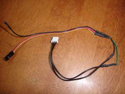
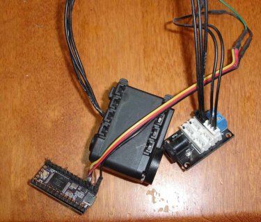
However for quick and dirty setups, Elmue's code should hopefully work fine. I often start off with a simple setup, for example here is one of my quick and dirty AX servo testing cables and setup:

Cheap_ax_cable.jpg simple-AX-servo-test-setup.jpg

It has a resistor soldered inline that connects to two wires, plus a ground wire. This type of setup should work with his code, by connecting the two pin connector to pins 0 and 1... Works with my code with just hooking up to pin 1.

So again, sorry if I got a little long winded here and wish him well!
 
I assume PULLUP drives the pin HIGH and OUTPUT_OPENDRAIN is unique ( uses the same PORT_PCR_ODE modifier as the provided code ).

Am I missing something doesn't Paul's added collector allow the OP code above to become:

Code:
#define TX_SERIAL 1

// Open Serial1 at 1 mega baud and in tristate mode
void Dynamixel_Serial1_Open()
{
    Serial1.begin(1000000, SERIAL_8N1);
    pinMode( TX_SERIAL, OUTPUT_OPENDRAIN );  // serial1_enable_TX_tristate(true);
}

// Send the instruction packet to the Dynamixel servo and then switch the TX pin back to tristate
void Dynamixel_Serial1_Write(byte* data, int count)
{
    pinMode( TX_SERIAL, OUTPUT );  // serial1_enable_TX_tristate(false); 

    for (int i=0; i<count; i++)
    { 
        Serial1.write(data[i]);
    }

    Serial1.flush(); // waits until the last data byte has been sent
    pinMode( TX_SERIAL, OUTPUT_OPENDRAIN );  // serial1_enable_TX_tristate(true);
}

Where this is the Pins_teensy.c code - unless there's a typo:
Code:
	if (mode == OUTPUT || mode == OUTPUT_OPENDRAIN) {
#ifdef KINETISK
		*portModeRegister(pin) = 1;
#else
		*portModeRegister(pin) |= digitalPinToBitMask(pin); // TODO: atomic
#endif
		*config = PORT_PCR_SRE | PORT_PCR_DSE | PORT_PCR_MUX(1);
		if (mode == OUTPUT_OPENDRAIN) {
		    *config |= PORT_PCR_ODE;
		} else {
		    *config &= ~PORT_PCR_ODE;
                }
	}
 
It always does that on any output - does that break usage for Serial? ::"1 is always the digital GPIO, and 2 to 7 are various peripherals"

Paul pointed me to the MUX(#) Ch. 10 pages in the manual - my first reading left me remembering enough to go back - but not comprehend all the details.

Indeed with Serial1.bring you get _MUX(3):
Code:
	switch (tx_pin_num) {
		case 1:  CORE_PIN1_CONFIG = PORT_PCR_DSE | PORT_PCR_SRE | PORT_PCR_MUX(3); break;
		case 5:  CORE_PIN5_CONFIG = PORT_PCR_DSE | PORT_PCR_SRE | PORT_PCR_MUX(3); break;

In that case indeed this OPENDRAIN change wouldn't apply for Serial# usage?
 
Back
Top