teency and sparkfun 7 segment serial display wont play well

Status
Not open for further replies.
SparkFun 7-Segment Serial Display - Red
COM-1144 and teency don't play well together

I have spent the last two weeks trying to get the display to work, I put the clock on a scope with the CS and don't see a problem I tried the "reset baud rate"
(int baudRates[12] = {2400, 4800, 9600, 14400, 19200, 38400,
57600, 7600, 115200, 250000, 500000, 1000000};
Serial.begin(baudRates); // Set new baud rate
delay(10); // Arduino needs a moment to setup serial
Serial.write(0x81); // Send factory reset command......

I can send numbers to the display but they roll on each set of writes, like this:
(send 0,1,2,3,)
display looks like this:
0,1,2,3
1,2,3,0
,2,3,0,1
normally I use the teency at work to do RADAR pulse syncing and stuff, just to show i use this stuff:
the first project was to display the trend of barometric pressure, and the "slammer" is a quad core pro mini that is used to see how long it will take to destroy some cables.
 

Attachments

  • slammer.gif
    slammer.gif
    104 KB · Views: 135
  • Baro trend.jpg
    Baro trend.jpg
    69.4 KB · Views: 120
Serial.begin(baudRates); // Set new baud rate
delay(10); // Arduino needs a moment to setup serial
Serial.write(0x81); // Send factory reset command......


Maybe you meant Serial1? Or Serial2 or Serial3? Can't see in the photos how the wires connect to Teensy.

But "Serial" on Teensy is always USB virtual serial, so writing to that will send the 0x81 byte to your PC, not to a serial display!
 
PSI transmit to a sparkun display https://www.sparkfun.com/products/11441


/*
2 11-2-2012
3 Spark Fun Electronics
4 Nathan Seidle
5
6 This code is public domain but you buy me a beer if you use this and we meet someday (Beerware license).
7
8 Serial7Segment is an open source seven segment display.
9
10 This is example code that shows how to send data over SPI to the display.
11
12 For more information about the commands, be sure to visit:
13 http://github.com/sparkfun/Serial7SegmentDisplay/wiki/Special-Commands
14
15 To get this code to work, attached an OpenSegment to an Arduino Uno using the following pins:
16 Pin 10 on Uno (CS) to CS on OpenSegment
17 Pin 11 to MOSI
18 Pin 12 to MISO
19 Pin 13 to SCK
20 VIN to PWR
21 GND to GND
22
23 */


#include <SPI.h>


int csPin = 10; //You can use any IO pin but for this example we use 10


int cycles = 0;


void setup()
{
pinMode(csPin, OUTPUT);
digitalWrite(csPin, HIGH); //By default, don't be selecting OpenSegment


Serial.begin(9600); //Start serial communication at 9600 for debug statements
Serial.println("OpenSegment Example Code");


SPI.begin(); //Start the SPI hardware
SPI.setClockDivider(SPI_CLOCK_DIV64); //Slow down the master a bit


//Send the reset command to the display - this forces the cursor to return to the beginning of the display
digitalWrite(csPin, LOW); //Drive the CS pin low to select OpenSegment
SPI.transfer('v'); //Reset command
}


void loop()
{
cycles++; //Counting cycles! Yay!
Serial.print("Cycle: ");
Serial.println(cycles);

spiSendValue(cycles); //Send the four characters to the display

delay(1000); //If we remove the slow debug statements, we need a very small delay to prevent flickering
}


//Given a number, spiSendValue chops up an integer into four values and sends them out over spi
void spiSendValue(int tempCycles)
{
digitalWrite(csPin, LOW); //Drive the CS pin low to select OpenSegment


SPI.transfer(1); //Send the left most digit

SPI.transfer(2);

SPI.transfer(3);

SPI.transfer(4); //Send the right most digit


digitalWrite(csPin, HIGH); //Release the CS pin to de-select OpenSegment
}
 
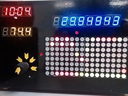
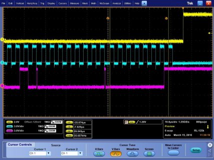
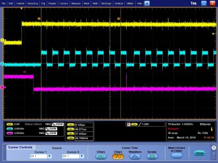
it seems to be a BAUD rate issue?: sending 8 bits took 28us for the Pro-Mini and 37us for the Teency. added 300us delay between writes and stabilized the display, but its not a good solution

#include <SPI.h>
//const int cs=5; //chip select
#include "Wire.h"
int analogPin = 0;
#define SPICLOCK 13 //sck
#define DATAIN 12 //MISO
#define DATAOUT 11 //MOSI
#define led 13
#define BlueLED 0
#define BlueBtn 1
#define OrngBtn 2
#define OrngLED 3
#define ASecnd 8
boolean i = true;//false
boolean j = true;//false
#define RTC 9 // Real time clock
#define ClockSelect 10 //ss10 clock display
int pin = 2;
int val = 0;

int Tempr=0;
#define I2C_ADDRESS 0x77
int AnaVal=10;

int digit3=1; //this is the display digits
int digit2=0;
int digit1=2;
int digit0=2;


void setup()
{
pinMode(BlueBtn, INPUT_PULLUP );
pinMode(OrngBtn, INPUT_PULLUP);
pinMode(ASecnd, INPUT);
pinMode(led, OUTPUT);
pinMode(BlueLED, OUTPUT);
pinMode(OrngLED, OUTPUT);
digitalWrite(led, HIGH);
digitalWrite(led, LOW);
Serial.begin(9600);
RTC_init();
//day(1-31), month(1-12), year(0-99), hour(0-23), minute(0-59), second(0-59)
// SetTimeDate(14,3,16,21,25,7);
byte clr;
pinMode(DATAOUT, OUTPUT);
pinMode(DATAIN, INPUT);
pinMode(SPICLOCK, OUTPUT);
pinMode(ClockSelect, OUTPUT);

pinMode( RTC, OUTPUT);

attachInterrupt(7, interupt, FALLING);//

digitalWrite(ClockSelect, HIGH); //disable device

digitalWrite(RTC, HIGH); //disable device

write_led_numbersClock(0x78,0x78,0x78,0x78); //Blank display
write_led_decimalsClock(0x18); // TIME COLAN ON 0X10= AM 0X18=PM


SPCR = (1<<SPE)|(1<<MSTR)|(1<<SPR1);
clr=SPSR;
clr=SPDR;
digitalWrite(led, HIGH);
}

void loop() {
j =digitalRead(BlueBtn);
digitalWrite(BlueLED, j);
i =!digitalRead(ASecnd);
digitalWrite(OrngLED, i);

Serial.println(ReadTimeDate());
delay(100);
int digit3=1; //this is the display digits
int digit2=0;
int digit1=2;
int digit0=9;
write_led_numbersClock(digit3, digit2, digit1, digit0); // the display looks like12:34

}


// Serial.println(ReadTimeDate());

void interupt() // interupt service 1 Hz
{
// digitalWrite(OrngLED, i);
}


//******************calls

void SetTime()
{

int digit3=1; //this is the display digits
int digit2=0;
int digit1=2;
int digit0=9;
write_led_numbersClock(digit3, digit2, digit1, digit0); // the display looks like12:34


}


//*****CALL****
void write_led_decimalsClock(int value)
{
digitalWrite(ClockSelect, LOW);
delay(10);
spi_transfer(0x77); // Decimal Point OpCode
spi_transfer(value); // Decimal Point Values
delay(10);
digitalWrite(ClockSelect, HIGH); //release chip, signal end transfer
}

//*****CALL****
void write_led_numbersClock(int digit1, int digit2, int digit3, int digit4)
{


digitalWrite(ClockSelect, LOW);
// delay(1); //was 10ms
spi_transfer(digit1); // Thousands Digit
delayMicroseconds(300) ;
spi_transfer(digit2); // Hundreds Digit
delayMicroseconds(300) ;
spi_transfer(digit3); // Tens Digit
delayMicroseconds(300) ;
spi_transfer(digit4); // Ones Digit
delay(1);
digitalWrite(ClockSelect, HIGH); //release chip, signal end transfer
}

//=====================================
int RTC_init(){
pinMode(RTC,OUTPUT); // chip select
// start the SPI library:
SPI.begin();
SPI.setBitOrder(MSBFIRST);
SPI.setDataMode(SPI_MODE3); // both mode 1 & 3 should work
//set control register
digitalWrite(RTC, LOW);
SPI.transfer(0x8E);
//0110 0000
//0110 0100 enable 1Hz
SPI.transfer(0x64); //60= disable Osciallator and Battery SQ wave @1hz, temp compensation, Alarms disabled
digitalWrite(RTC, HIGH);
delay(10);
}
//=====================================
int SetTimeDate(int d, int mo, int y, int h, int mi, int s){
int TimeDate [7]={s,mi,h,0,d,mo,y};
for(int i=0; i<=6;i++){
if(i==3)
i++;
int b= TimeDate/10;
int a= TimeDate-b*10;
if(i==2){
if (b==2)
b=B00000010;
else if (b==1)
b=B00000001;
}
TimeDate= a+(b<<4);

digitalWrite(RTC, LOW);
SPI.transfer(i+0x80);
SPI.transfer(TimeDate);
digitalWrite(RTC, HIGH);
}
}
//=====================================
String ReadTimeDate(){
String temp;
int TimeDate [7]; //second,minute,hour,null,day,month,year
for(int i=0; i<=6;i++){
if(i==3)
i++;
digitalWrite(RTC, LOW);
SPI.transfer(i+0x00);
unsigned int n = SPI.transfer(0x00);
digitalWrite(RTC, HIGH);
int a=n & B00001111;
if(i==2){
int b=(n & B00110000)>>4; //24 hour mode
if(b==B00000010)
b=20;
else if(b==B00000001)
b=10;
TimeDate=a+b;
}
else if(i==4){
int b=(n & B00110000)>>4;
TimeDate=a+b*10;
}
else if(i==5){
int b=(n & B00010000)>>4;
TimeDate=a+b*10;
}
else if(i==6){
int b=(n & B11110000)>>4;
TimeDate=a+b*10;
}
else{
int b=(n & B01110000)>>4;
TimeDate=a+b*10;
}
}
temp.concat(TimeDate[4]);
temp.concat("/") ;
temp.concat(TimeDate[5]);
temp.concat("/") ;
temp.concat(TimeDate[6]);
temp.concat(" ") ;
temp.concat(TimeDate[2]);
temp.concat(":") ;
temp.concat(TimeDate[1]);
temp.concat(":") ;
temp.concat(TimeDate[0]);
return(temp);
}
char spi_transfer(volatile char data) //SPI Bus setup
{
SPDR = data; // Start the transmission
while (!(SPSR & (1<<SPIF))) // Wait the end of the transmission
{
};
return SPDR; // return the received byte
}


/* if (Thours10==1)
{write_led_numbersClock(digit3, digit2, digit1, digit0);} // the display looks like12:34
else
{write_led_numbersClock(0x78, digit2, digit1, digit0); } // the display looks like 1:23
*/
 

Attachments

  • pro mini 28us.jpg
    pro mini 28us.jpg
    209.1 KB · Views: 80
  • teency 37us for 8 bits.jpg
    teency 37us for 8 bits.jpg
    207.9 KB · Views: 102
O.k. A couple things. I have the same display and have successfully used it with a T3.1, The display works fine using one of the T.3 Serial ports for input. I used Serial2 for my effort. Also the display does need some form of cursor control. For my application I reset during the setup loop and then always print 4 numbers to my 4 digit display so I never developed a more complicated scheme than that.

Here's the pertinent code fragments (the whole program is long an mostly unrelated)

Code:
#define Serial7Segment Serial2
byte brightnessLevel = 100;
char tempString[10]; //Used for sprintf

void setup()
{
  Serial7Segment.begin(9600); //Talk to the Serial7Segment at 9600 bps
  delay(1500);
  Serial7Segment.write('v'); //Reset the display - this forces the cursor to return to the beginning of the display
  brightnessLevel = 100; //100% brightness
  Serial7Segment.write(0x7A);  // Brightness control command
  Serial7Segment.write((byte) brightnessLevel);  // 0 is dimmest, 255 is brightest
}
int team = 12;
void loop()
{
  sprintf(tempString, "%4d", team); //Convert deciSecond into a string that is right adjusted
  Serial7Segment.print(tempString); //Send serial string out the soft serial port to the S7S

}

The above compiles but I did not test it past that at the moment. It should work if you connect the device to the Serial2 pins no need to mess with SPI

Cheers Kb
 
Status
Not open for further replies.
Back
Top