Custom Teensy Startup Question

Status
Not open for further replies.
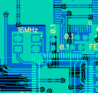
How does this look?

Capture2.PNG

I'm still a bit confused about the crystal's ground plane. In Paul's description it makes it sound like it shouldn't be connected to ground at all but in all the examples I've seen there is a via or trace connecting it to the main ground planes. Am I just reading that incorrectly?
 
No need for a double GND connection on the crystal. Just connect from the underside / inside. Use the outside connection for pin 31 for decoupling cap on pin 30,31. Pull that cap closer and run power line through it before hitting pin 30. Otherwise you give up some of the benefit of cap re EMI noise reduction.
 
Sorry I'm not clear on what you mean by inside vs outside.
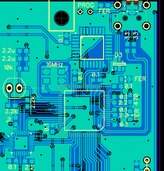
Is this close?

Capture3.PNG

If not is there an example you can point me too?
 
Looks like it ought to work.

Are you sure it's really the crystal?

If you're doing another board rev and care about costs, maybe consider switching to the less expensive KL02/KL04 chip?


Edit: I replied to a private email (basically saying I posted here on the forum), but my email reply bounced. @john-mike - if you didn't already know, there's some sort of problem with your email service.
 
Last edited:
Are you sure it's really the crystal?
No but I'm trying to rule that out now.

This isn't the first device we've made with the MINI54 and MK20. The first had a way sloppier layout and in the 500 units we produced had very few that wouldn't program.
All of the revisions of this board have had this issues though. Obviously very frustrating!

consider switching to the less expensive KL02/KL04 chip?
Yes I was thinking of doing that. What other advantages does it have?

email reply bounced
Yeah we've been having issues and are trying to change servers now. Could you reply to jmreed@gmail.com? Thanks!
 
Last edited:
Eventually the Mini54s will run out and we're probably going to discontinue them. No need to panic yet, but long-term the KL02/KL04 is the future. It's also less expensive, and comes physically smaller if you care about board size, and physically larger for easier hand soldering. The quality of the part is also much, much better.

When/if more features are added to the bootloader, only the new chips will get the new features. I never want to touch another Nuvoton microcontroller again!
 
Ok I'll make the switch.

Do you have an visual example of the crystal layout you described, Paul?

Anything else that might be causing this? I've tried uploading from several different win7 and osx machines.
 
Last edited:
See post #2 for one way to route the mkl02 without any ground plane penetrations. Did cheat by using two 2010 jumpers, however.
 
I think I'll go with the MKL4 since I have the space.
Thanks again.

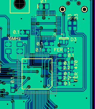
One last thing @PaulStoffregen, For the MKL04, does the PTA6 signal still connect to the ID pin of the USB?

Capture 4.PNG
 
I think I'll go with the MKL4 since I have the space.
Thanks again.

One last thing @PaulStoffregen, For the MKL04, does the PTA6 signal still connect to the ID pin of the USB?

Not Paul, but yes if you want USB Host Mode, see post #2 in this thread:
Constantin said:
Unless you are expecting to use this device as a USB master, you can simply GND the USB ID line at the USB connector. You still want to connect PTA6 on the bootloader and PTA1 on the MK20, however.

It sounds like you've definitely seen the T3.2 schematic: https://www.pjrc.com/teensy/schematic.html. The MKL02 and MKL04 have the same connections (of course pins move, but same port/bit).
 
Status
Not open for further replies.
Back
Top