DAC output voltage scaling

Status
Not open for further replies.

hermes365

New member
Hi all, I'm trying to use the DAC on a Teensy 3.1 to generate a pulse train at a desired frequency, amplitude and pule duration to control a laser driver that modulates based on an applied analogue voltage (technically this requires 0-5V, but I'll deal with that later). In the attached code, the user inputs these parameters over a serial line, and then types 'GO' to initiate the sequence. Pulses are then output, terminated by a brief ramp down at the end of each. This works well, except for the amplitude of the pulse, which given a user selected value between 0~1 should scale the 12bit DAC between 0~4095, and be output as 0~3.3V on A14. The proportional scaling works using the method, but the DAC won't output more than ~0.25V. I've tried various options to change Vref, and don't think it's a (int) casting or 'map' issue as printing amp_ (the 0~4095 scaled integer amplitude) value to the serial comes up correct. Am I missing something? How can I get a full 0~3.3V output on the DAC? The Teensy is powered over USB.

Many thanks for any insight/advice!
Cheers,
Aleks
 

Attachments

  • PulseSequencerAnalogueRampDown.ino
    3.2 KB · Views: 268
Your code uses analogReference(INTERNAL), which should set the maximum to 1.2V. Use analogReference(EXTERNAL), or just delete it, for 3.3V scale.

The DAC output is weak, only a couple mA is available. Perhaps your circuit is too much of a load? Maybe you'll need an opamp to buffer the output to a stronger drive? An easy way to check is just measure the voltage and disconnect whatever you're driving. If the voltage increases or changes when you disconnect the load, then you almost certainly need an amplifier to buffer the signal.
 
Thanks Paul. I have played around with this. Changing the analogReference as you suggest doesn't help things. Currently I have A14 directly coupled to an oscilloscope looking for the DC offset change. As you point out I do plan to buffer the output signal for the final application but expect to see a full scale voltage swing in this configuration.... Any ideas? - many thanks, Aleks
 
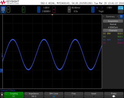
As a quick sanity check, I ran this just now on a Teensy 3.2 using Arduino 1.6.8 with Teensyduino 1.28-beta1:

Code:
// Simple DAC sine wave test on Teensy 3.1

float phase = 0.0;
float twopi = 3.14159 * 2;
elapsedMicros usec = 0;

void setup() {
  analogWriteResolution(12);
}

void loop() {
  float val = sinf(phase) * 2000.0 + 2050.0;
  analogWrite(A14, (int)val);
  phase = phase + 0.02;
  if (phase >= twopi) phase = 0;
  while (usec < 500) ; // wait
  usec = usec - 500;
}

Here's the waveform I see on the DAC pin.

file.png

If you're seeing something different, odds are strong your hardware's been damaged.
 
I've previously been able to get that to work on this board, but no longer :( Looks like I'll have to order a new board. Many thanks for your help though Paul, truly appreciated.
Best wishes,
Aleks
 
Status
Not open for further replies.
Back
Top