Idea for a not as Teensy Teensy

Status
Not open for further replies.

rjfon1

Active member
Good Morning all.
Possibly setting myself up for a flaming, but here goes.
Love the Teensy and what it does, but it's so damn small (Yes I know, hence the Teensy name)
I'm pretty sure there would be a market for a more versatile version.

My thoughts are the following:

Similar format i.e: pins on three sides, but no surface mount connections on the bottom as in the current Teensys;
All IO pins on the outside;
One pin in for each IO,i.e.:2.54mm; (1)
The next pin in is a +V 5V (2)
The next pin GND (3)
If the pin is Analogue capable, the next pin is a Analogue AREF; (4)
The above format would allow direct connection of servos and easy connection to switches & potentiometers;

Eg: 1,3 is a switch or LED or PWM device.
1,3,4 is a potentiometer

An onboard LED for every pin, similar to that used on the current Pin13 (Don't know if that's possible, either hardware wise, but may just need an addition to coding). Allows for easier prototyping.
A higher current 3.3V, and 5V regulator to power outputs via transistors;
SMD Transistors and if required diodes to allow a greater overall output per channel attached to each output using the transistor to reduce current workload on the CPU;
DIP switches onboard to negate track cutting, such as VIN/VUSB;

The above would probably fit on a circuit board about double that of the current Teensy 3.X.

Personally I would think the above would be more versatile with only minimal increase in PCB realestate.

OK guys and gals, let the flaming (err, comments) begin.

Rob.
 
I'm trying to understand whether you're asking for help to make this yourself, or you're suggesting or hoping someone else would make it and you wish to have one? (or some other quantity?)
 
G'Day Paul.
You're always first off the mark.
This is something that I would certainly have use for, but I'm thinking of the wider community, such as, in my case, flight simulators, or other cases, experimenters, robotics, 3Dprinting without the need for external cards, etc.
If there is a huge response, and or suggested market, then the seed planted would be free for anyone to use. As for myself, it would be a lot of work and learning curve to try to get this going, (not saying I couldn't, but with full time work, kids, and my sim, I'm running a bit time poor) but others with the available current and available resources could probably start off with your initial design and modify the schematic on one night, and do the PCB on the next, off to the manufacturers the next.
The only additional components I see as being necessary would be the 2 regulators, power socket, extra LEDs, resistors, diodes and headers. I work it out to be <$5 extra per board.
It's just food for thought. Someone might make something of it. It may or may not be worth your while. The Teensy is still the best/simplest product available at the moment for its purpose. Thanks Paul.

Thanks,
Rob.
 
To my mind this is a not a new teensy, this is a shield concept.

You could pull out all the extra pins you want easily, duplicate AREF pins, 5v, GND etc and locate LEDs that way (I won't comment on their potential interference with operation!), all without having to fully manufacture a niche version of the teensy.

It's interesting as you see your version as more versatile, I see it as a much less versatile niche product in comparison, however I can see the usecase for it.

IT might make a good 3d printer / CNC motherboard for example, but would be way too big and heavy for a drone.

It's something you could probably design yourself with a slot to plug the Teensy into it?
 
I would much prefer this board over the one presently being sold by OSH Park. I need easy access to pins far more than small size.

I've been considering getting a batch of these made up, but every time i do, I look at the 3 or four different breakout solutions and I ask myself why again.

If hundreds of people were interested it might be worth it, but they'd be much more expensive than a teensy and wholly unsupported by PJRC.....I'm not sure what it would achieve.

So every time I think about it, I ultimately decide it's a stupid idea.
 
I have four of the OSH v3.2 boards and they're adequate for my present project. However, I have a project that uses a Mega and I would like to convert it to a Teensy but my shaky hands are not good for soldering to the underside pads. I have enough trouble with the header pins. There is another board that makes connection to the square pads but leaves a few others unconnected.

I wonder what the cost would be for the long four layer finished board. I still see that as the ultimate solution. However, as you say, the present version will solve most problems.
 
I'd buy one - because it has the SWD lines available and the teensy doesn't.
Yep - I wish PJRC would release a set like this Teensy 3.2+ It would make it easier to build my own shields. But then again I am hoping the Paul is working on the new Teensy board :D

I have built a few different shield boards for my own fun, and you find out that there many valid possibilities for each option. Example 3 pin headers - What voltage do provide to the middle pin? +5v is great for many sensors, some others maybe want +3.3v. But if you are wanting to run RC servos, then you probably want Vin... So several of my boards had jumpers for 4 pin groups. Likewise for Analog capable pins, are you wanting to use them as Analog pins or do you want to use some of them as digital pins? ...
 
This is exactly the kind of controller layout I had in mind when I posted on the carrier board thread.

The logic is simple - there are two typical uses for controllers: breadbording/prototyping and final product. For the former having access to all the pins is essential and far outweighs the benefits of small size. For the latter the convenience of having ground and power pins next to signals is very important. In most cases these pins are the only extras necessary. For this reason building custom boards or soldering breakout boards only to have convenient connections does not make much sense.

How about this - what if new Teensy would have two supply rails on both sides along the signal pins, holes only. Either a groove or slots in PCB would separate these rails from the "normal" Teensy outline. Should not add much cost in production. Then if one wants to use servo connections they can install corresponding pins and power the rails from either VCC, VIN or AREF. If, on the other hand, smaller package is required then they would simply break away the sides and have regular-sized controller.
 
Last edited:
some thoughts ( hav'nt read the whole thread):

- With Pauls "Pulse Position" library (https://www.pjrc.com/teensy/td_libs_PulsePosition.html) you need only two pins to drive up to 16 Servos. More are possible, with more pins.
You'll only need two 74hc(t)164 (you can buy them in DIL, too and just use a breadboard.. should work even with shaky hands(?) )

For only two pins (ok, + GND), is special "teensy addon board" really needed ? Perhaps an own, separated servoboard, ok..

VIN is mentioned a bit too often :) VIN is a reall bad idea, if you want to use it as OUTPUT.
Servos can take some A (not mA) of power (esp. the bigger ones) easyly. Each of the 16.
USB can give 500ma max.. so you need an own supply for the servomotors anyway.

Just my 2 cents :)
 
Last edited:
- With Pauls "Pulse Position" library (https://www.pjrc.com/teensy/td_libs_PulsePosition.html) you need only two pins to drive up to 16 Servos. More are possible, with more pins.
You'll only need two 74hc(t)164 (you can buy them in DIL, too and just use a breadboard.. should work even with shaky hands(?) )
For only two pins (ok, + GND), is special "teensy addon board" really needed ? Perhaps an own, separated servoboard, ok..

If all MCU pins are routed to Teensy pins then you'll be hard pressed to find a case where multiplexing like that is necessary. And that is exactly the reason for OP suggestion. And yes, in most cases it eliminates the need in addon boards, breakout boards and such. In rare cases where additional electronic components required making custom Teensy board is of course justified, but it was my impression that OP was trying to minimize the number of those cases.

VIN is mentioned a bit too often :) VIN is a reall bad idea, if you want to use it as OUTPUT.
Servos can take some A (not mA) of power (esp. the bigger ones) easyly. Each of the 16.
USB can give 500ma max.. so you need an own supply for the servomotors anyway.

With the exception of prototyping time not many controllers that drive servos are powered from USB. In the final products (robots, drones) they are typically powered from either BEC or straight from the battery, which makes connection of power bus to VIN a perfectly good option, providing you have wide enough traces on PCB of course. Having said that, I would not suggest permanent connection to VIN. As I suggested in the post above I'd rather leave it to user to make a choice, or maybe add some pads on the bottom for solder-jumpers to select which of the Teensy voltages those rails will be connected to.
 
As I mention, in many case many of my boards I have experimented with, have 3 pin headers, which I do find convenient. I personally don't think PJRC should not add this on their default chips... Now it would be great if someone sold an assembled board where you could plug in a Teensy 3.2, which adds these capabilities or

Again as I mentioned, there are to many valid options for what I may want. Example for the most part I don't use RC servos any more, I prefer Dynamixel servos. So again in majority of the time I won't need VIN going to the pins. But do you choose 3.3v? or 5v? if so how much current should these source? Should I be able to source X-bee plus several external sensors? Note: I often times add something like a 1.5amp switching regulator (811-2692-ND) to my boards. Do you add this to default Teensy? These go for something like $3.78 each if you order 100 of them. So how expensive should the new Teensy be?

Also it does come with a pretty big size increase:
Current one is something like 1.4"x.7" (.98 square inches) if you now say that you want all all power signals brought out to the outside with 3 pin headers. The Teensy 3.2 has maybe 14 signal pins, which are either 2nd row (A10,11) or Surface mount (A12,3,24, 25, 26, 27, 28, 29-33), so this may extend the chip by .7" length wise, and we add .4" for power and ground pins on both sides, so now 2.1x1.1 (2.31 square inches) so well over twice the size.

Other issues: suppose I might want to breadboard these boards... Can't if you have pins with signal/ground and power all going to same row on breadboard.

So again I think it would be great if someone built some standard expansion board Teensy boards, but I am not sure it makes sense for all of these features to be added to the default chip.
 
Morning All.
Being on the other side of the Pacific, my reply timing is usually pretty crappy.

Many valid points have come up. I'll try to cover most.

Arctic Eddie-That Teensy ref board on OSHPark is getting to where I was thinking. Everything is available, on all of the side pins.

Pensive- I see your point stating it's more of a shield project, but the issue is not creating a shield, as a shield is generally something that is plugged/piggybacked onto the CPU board. In this case, yes you can piggyback a Teensy 3.x, but the problem is you still don't have access to the pads on the bottom. In this case you have to first attach a breakout board such as this https://www.oshpark.com/shared_projects/UI47TwNf and then put the shield on top of it. The only way to do this would be to use the long leg female through headers if you want to use a shield, or place the board into a breadboard, or mount the shield underneath, as in reality, this is not possible, as you can't use female headers on top, as you need to solder onto the top.
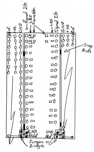
I wouldn't really say this is a niche product at all. It is simply easing the use for a greater community. Each pin has a use- a (1) input(digital/pwm/analogue/data) or output(digital/pwm/analogue/data), (2)GND, (3)+V(3.3, 5, other), (4)Aref. This is the same for every person. (1) &(2) are required, (3) & (4) are optional. If the Teensy3.2Mega (I'm not putting a copyright on this) was built the same as the Teensy board, populated except for the headers (I would personally use the new colour coded headers (Red-+V, Blk-GND, White-Signal, Yellow-Ref)), then the weight increase would be negligible to anything but a very small drone. Overall, the size would be length-same as the Teensy Ref DIY board from OSH, width would increase by 4 header holes per side, plus diode,resistor,LED, transistor (These weigh about .008grams each, and LED resistor diode are available in 0402 SMD size), and the board would still be way smaller than the mega2560. Personally I would still include the LED as it good for testing/faultfinding.

KurtE-As far as the middle pin is concerned, this could easily be overcome with a single addition input pin attached with traces to the middle pin of each, appropriately sized to handle the necessary current. As mentioned by wwwoholic, you can then make your own choice.

WWWoholic- the snap away is a good thought. It allows for freedom to use/ignore as required.

Attached is a thought concept.
Thanks for listening.

Teensy 32Mega.jpg
 
Another option would simply be to get the 3.2 breakout available on OSHPark, and create a new breakout with the above features.
 
Other issues: suppose I might want to breadboard these boards... Can't if you have pins with signal/ground and power all going to same row on breadboard.

that is not a problem at all. You have 3 options here:

1. If you do not need servo connections you do not solder in those pins. As simple as that.

2. If you want servo connections AND breadboard you can use readily available long pins that will stick out down and up at the same time for signal holes and normal pins on top only. Then you can plug Teensy into breadboard and connect servos at the same time.

3. Finally as I suggested above there can be a groove or slots that allow easy detaching those side bars with power rails. You will then have just a "normal" Teensy on hand.

Also let me point out that we should not focus on servos here. 3-pin connectors are useful for wide array of external devices, like analog and digital sensors, various level shifters and adapters etc.
 
Another option would simply be to get the 3.2 breakout available on OSHPark, and create a new breakout with the above features.

Yes, this.

The reality of modern SMT manufacturing is the economy of scale. Especially for moderate volume products like Teensy, we just can't pour PJRC's limited resources into different form factors. These sorts of things are best done by breakout boards.

While perhaps a little off-topic, I should mention Massimo Banzi has recently made some public comments that Arduino may be moving towards a smaller form factor. So far, they've only just recently released 1 product (MKR1000) in this new form factor, and Adafruit has numerous "feather" products. Perhaps official Arduino shields are coming?
 
LOL!

I love the Teensy form factor; it is just about perfect, which is why we kept it for our STM32L4-based Arduino-compatible MCU breakout.

But maybe there is a market for boom-box-sized MCU boards?
 
it wouldn't be "teensy" anymore..
to make it larger, you can use one of the addon-boards. or make your own.
but you can't make a "fatty" smaller....

i don't want a fatty :)
 
Thanks guys for the replies.
Paul- I fully understand this, and the initial email was to find out possibilities. If it was a resounding Yes, then I'd say can you build it for the masses.
Frank B- Now lets see you make the shields for that one.
-No, it wouldn't be Teensy, but Teensy-ish.
When I got my first order from Littlebird in Australia, I ordered 3x Teensy 3.1. It was sent through in a box about the size of a double audio CD case(the old style). Opened the package and pulled out the packing, the laminated pinots card, and no Teensys. I thought what the. Looked through everything and finally found the little packets. The size blew my mind. So used to the mega2560, and then seeing the Teensy on a large screen, didn't realise it.
Stevech- They say it doesn't, but we all know it does.

In the end, I think that a breakout will be the go. I will try to source some freewarePCD design software (MAC), and download the OSHpark 3.2 breakout gerbers and try to make it up. It will take time. I have the freeware version of Eagle, but haven't used it much. Haven't worked out if you can import the berbers directly, or compile and convert.

Thanks guys.
Rob.
 
I believe there may be a need for a large breakout board that uses rugged protection circuits and screw terminals. Several times I've considered making such a board... but I've been pretty focused on stuff like the Prop Shield and upcoming K66-based Teensy, and adding software features like the recent USB additions. Once we start shipping the K66 chip, I'm going to have a *lot* more software work to do! My hope is OneHorse and others can make these sorts of breakout boards. That really lets me keep focusing on the software side.
 
Those PJRC prototypes (at least this one:: Teensy 3.2 DIY Reference Board) look like they could be the basis of a Teensy_SR Family. Where SR stands for Shield Ready. Given how it had all the pins laid out in a through hole fashion - versus under pads.

With an awesome new PJRC Teensy board (or two) coming out - fresh and new - tested to your standards - an assumed (maybe even 4 layer?) Proto version might ideally/easily mount to a shield base and offer full utility and have a long life ahead. Since the things will already be a huge 2.4"(++) - a Shield Ready family wouldn't grow them as much even going to UNO size - and give 100% utility in an easier to fit aftermarket ready SR version.

<edit>: Longer than a 2.5" UNO the T_3.2 DIY board is:: 4 layer board of 2.80x1.00 inches - but might fit in the 2.25" width of this board and just need pins/headers.
 
Last edited:
Status
Not open for further replies.
Back
Top