Teensy 3.2 Midi Controller Problem with "jumping" CC Values

Status
Not open for further replies.

FelixButt

Member
Hey guys,

so yesterday i had a couple of questions about the teensy as a midi controller.
Today, i soldered the parts together and it went pretty well (no parts are touching and everything seems to be soldered correctly to the Teensy).
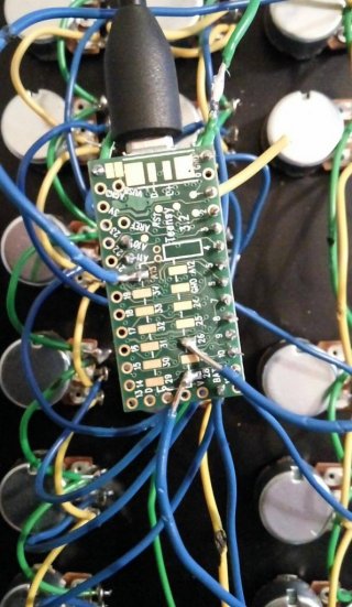
13105906_1176799898997805_521570636_o.jpg

The Teensy does in fact send Midi CC Values, but here comes the problem: whenever the Teensy sends midi signals, those CC Values "jump" between 1-16 in a fraction of seconds, means it doesn't stick to one Value.

Since im really just a musician who wants to build a custom Midi Controller, i looked up the code that was recommended on the PJRC website.
I defined how many analog inputs i have (16) and left the rest as it is. I tried a few other codes, which did not have that "jumping" problem of the CC Values, but they didn't work for me either.

Code:
 // define how many pots are active up to number of available analog inputs
#define analogInputs 16
// make arrays for input values and lagged input values
int inputAnalog[analogInputs];
int iAlag[analogInputs];
// make array of cc values
int ccValue[analogInputs];
// index variable for loop
int i;

void setup() {
  // MIDI rate
  Serial.begin(31250);
}

void loop() {
  // loop trough active inputs
  for (i=0;i<analogInputs;i++){
    // read current value at i-th input
    inputAnalog[i] = analogRead(i);
    // if magnitude of difference is 8 or more...
    if (abs(inputAnalog[i] - iAlag[i]) > 7){
      // calc the CC value based on the raw value
      ccValue[i] = inputAnalog[i]/8;
      // send the MIDI
      usbMIDI.sendControlChange(i, ccValue[i], 1);
      // set raw reading to lagged array for next comparison
      iAlag[i] = inputAnalog[i];
    }
  delay(5); // limits MIDI messages to reasonable number
  }
}


How can i solve this problem?
 
So you have used pins 1 to 16 in strict order (that code reads pin 1, then pin 2, then pin 3)?. Is everything grounded properly? Do all the pots jump? what is their rated resistance?? 10K? The pots in your picture look a bit like guitar pots ... are they 250K??

Try increasing the deadspot

Code:
if (abs(inputAnalog[i] - iAlag[i]) > 11){

Try reducing the deadspot...!!

Code:
if (abs(inputAnalog[i] - iAlag[i]) > 3){


I would check your wiring ... and then I would just print out the raw values from each input in turn in the serial monitor, as a sanity check.
Code:
void setup() {
  // MIDI rate
  Serial.begin(31250);
}

void loop() {
    Serial.println (analogRead(1)); // read the pot on pin 1 and print ....
    delay(20);
    // open the serial monitor in the arduino ide, 
    //and see if the pot is giving a stable reading.
    // I would expect stable to be less than + / - 4 at rest ...
    // Then for the next pot change it to "analogRead(2)" (the pot on pin 2). 
}

From there you can work out what a good deadspot size would be
 
Last edited:
@FelixButt those hanging solid wires on the bottom pads scare me - I got a 50 cent speaker and soldered solid wires to the one pad - about the third time I touched it the pad popped off. Luckily it was a Chinese 5 pack for a couple bucks.

I'm sure the Teensy is somewhat better and the pad as solid as it can be . . . but abused wrong and it could pull off.

There are simple PCB adapter boards that will bring the pads out to a through hole - I used one linked here
 
i just had a thought ... are the pots linear taper or log taper??? maybe that could have a radical effect??? i will look it up on the interweb.
 
@Adrian, the pins i used are actually not a A0-A15, but A0, A1 , A2, A3, A4, A5, A6, A7, A8, A9, A10, A11, A13, A14, A15, A17.

Sorry for a kind of a dumb question, but is the VIN Pin that says 3,3 to 6 Volts the one that im supposed to wire my power line to ?


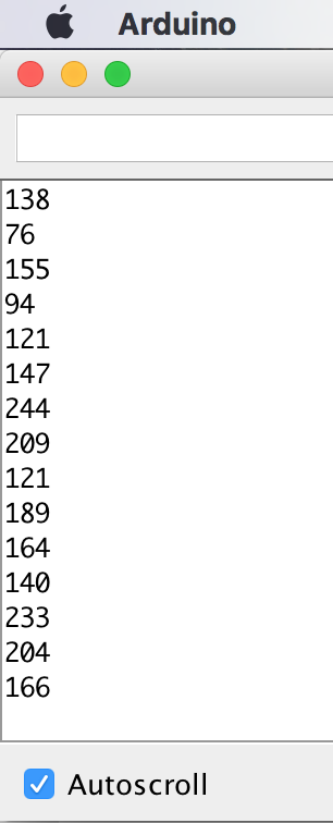
These are the numbers that are shown to me when turning on the serial monitor:

Bildschirmfoto 2016-04-27 um 17.57.29.png

it just keeps writing numbers over and over and it doesn't stop.
 
Last edited:
Couple suggestions, you can use a 3.3V output for the top of the pot if that's easier, but see that small via labeled AREF in the top left? That's where you want the high side of your pots connected. Similarly, you want the low side of your pots connected to AGND, which I also see is not soldered. Paul added ferrite beads and filters to the analog voltage supplies on the board for that reason, does a good job to clean up the analog signals.

After that, scale your ADC values to the proper size using :

analogReadResolution(7); //Since you say this is for a MIDI device, you won't need more than 7 bits. If you're doing 14-bit midi controls, then yeah, set it to analogReadResolution(14);

then, I would add in some averaging which is also nicely built into the Teensy core library :

analogReadAveraging(8); //Can start with 8, go up or down depending on how much latency is acceptable, options are only 0,4,8,16,32 for averaging, I believe this is actually done in the hardware of the MK20 chip, which is pretty cool.

If you're still noisy... your wiring is just bad somewhere. Hope this helps.
 
@capricorn one Are you saying that AREF is better than 3.3V? I did not know that .... thankyou! And I never knew about inbuilt averaging ... i use my own routine ... I will give inbuilt averaging a go ... could simplify my code! thanks! I use deadspots atm. Seems to suppress jitter, but probably looses resolution ...

btw a .10nf - 1.00nf cap across ground and the wiper might help with noise too, according to some posts (never tried it myself).

@FelixButt ... those numbers are supposed to repeat continuously ... they look almost like there is nothing attached to the pin!! not what you would expect with a pot attached at all ... check your wiring ... there is like over 100 difference between low and high ... that is a lot of noise.
 
Last edited:
@adrian I believe AREF is better, check out the schematic, it's coming after the 470ohm/.1uF low pass filter, so keep in mind there will be some voltage divider effects if you load it with too small of a pot. But I consistently use it for my pot voltage supplies with good results. Certainly a good idea to use AGND though which has the added ferrite bead to GND for filtering out noise. As for the averaging, it's pretty sweet, works well for me!

@FelixButt one more thing I remembered when writing this, you might want to throw some .1uF caps across the signal->GND pins of your pots, that will also reduce the jitter. Typically I would do this on the board side, but from your picture, I think putting it across the pot would be easier.
 
@adrian okay now you've got me wondering if that's the wrong way to use AREF. I mean it definitely works either way in this case, but I'm thinking the reason the 470 ohm resistor there is so that you can provide your own AREF value without shorting the two voltages together. Paul would have the right answer for that one. I'm thinking maybe connecting to AREF might ultimately be a bad idea because it's the reference for the ADC, so you'd want that to be stable, and a known value in the even that you're reading analog voltages somewhere else where you need to know the precise value of AREF. But in this case, where it's just pots connected, and the value of AREF is somewhat arbitrary, it's probably the cleanest voltage source for the analog voltage pots. That make sense?
 
from paulstofreggen:

AREF is used for connecting a highly accurate external reference voltage. You'd use that when you're measuring specific voltages, and when you need better accuracy than the pretty decent built-in reference can provide. (or on Teensy-LC, where there is no built in ref...)

Normally pots are connected between 3.3V to AGND (if using Teensy 3.2), or 5V to GND (if using Teensy 2.0). You do *not* want to use AREF for pots! You want the measurement reference to be the power supply, which is the default setting. If the power supply fluctuates, the measurement range fluctuates. For pots, that's exactly what you want, because the voltage from the pot will fluctuate the same way. The net result is most variability in the power cancels out. If you used a stable AREF or internal ref, you'd actually measure any changes in power to the pot, instead of automatically canceling them out.

Of course, if you have some sort of sensor that gives an accurate voltage, then you'd want a stable reference. The built-in reference is good enough for many uses, so the AREF pin tends to only get used in the most demanding analog projects. But for pots and other resistance measurements using the power supply, a stable reference that doesn't track power supply changes is actually bad.
 
I really just want to not say anything, because I feel like it's best to just follow that advice, but for my own sanity, can you clear this up for me?

You want the measurement reference to be the power supply, which is the default setting. If the power supply fluctuates, the measurement range fluctuates. For pots, that's exactly what you want, because the voltage from the pot will fluctuate the same way.

That's what I was implying earlier where since it's only pots being used and not accurate voltage readings, it's okay if AREF changes, as long as all the pots have the same reference. However, this does not work as I was expecting if the AREF setting for the ADC is the internal voltage reference. It ONLY works if AREF for the ADC is set to external. Now, I thought that AREF as external was the default case, but according to what Paul wrote there, AREF is set to internal ref by default. Can you confirm that was a recent post regarding the current Teensy? Because looking at the analog reference in core_pins.h it looks like the DEFAULT setting is the same as the EXTERNAL for Teensy 3.1 & 3.2, but is set for INTERNAL for Teensy LC.
 
That was easy to find - fluctuates is a unique word - even the forum search brought it right up - often it takes a BING search :

Can-you-have-more-than-two-Pots-on-the-AREF-pin

01-03-2016, 05:57 AM >> nothing changed since then

(Adrian - if you do a "reply with quote" - the generated reply text can be selected and copied - cancel the edit - and then pasted in the new thread - the LINK in the header follows and will go right back to the source thread I've discovered -

AREF is used for connecting a highly accurate external reference voltage. ...
 
thanks defragster. back to OP ... the numbers look like like a drifting pin, I think .... that is just too much to be noise ... so it looks like wiring .... looking at the code.... is it right that analogRead(1) and digitalRead(1) read different pins ??

The OP code loops through the pins in order, but "0,1,2,3 etc" in the context of analogRead(x) actually mean analogRead(A0 .....A3...) etc> So the code seems right?

in other words

Code:
void setup() {
  Serial.begin(31250);
}

void loop() {
    Serial.println (analogRead(A1));     
    delay(20);
}
is the same as

Code:
void setup() {
  Serial.begin(31250);
}

void loop() {
    Serial.println (analogRead(1));     
    delay(20);
}
?? Something is screwy... must be wiring ... or maybe 'overload'?? Getting one pot working with no others attached sounds like a good plan to me ....
 
I just looked at the sketch _ I wondered about the pin mapping myself ... indeed 0 is mapped to 14 to get analog when I doubled the internal code for() loop and read #14-23 as well as #0-9.

I only have the top 10 analog inputs handy. I wired three to 3.3V and two to ground and this simplified version showed what I expected to serial output?

Code:
#define analogInputs 10
int inputAnalog[analogInputs+30]; // opps - wasn't big enough as written below
// index variable for loop
int i;

void setup() {
  Serial.begin(31250);
  while ( !Serial && (millis() < 4000 ));
}

void loop() {
  // loop trough active inputs
  for (i = 14; i < (14 + analogInputs); i++) {
    // read current value at i-th input
    inputAnalog[i] = analogRead(i);
    Serial.print( i );
    Serial.print( "==pin, val==" );
    Serial.println( inputAnalog[i] );
    delay(25);
  }
    Serial.println( "-------" );
    Serial.println( "-------\n" );
  delay(5000);
}

14==pin, val==0
15==pin, val==0
16==pin, val==37
17==pin, val==1023
18==pin, val==1023
19==pin, val==337
20==pin, val==223
21==pin, val==1023
22==pin, val==230
23==pin, val==96
-------
-------
 
Last edited:
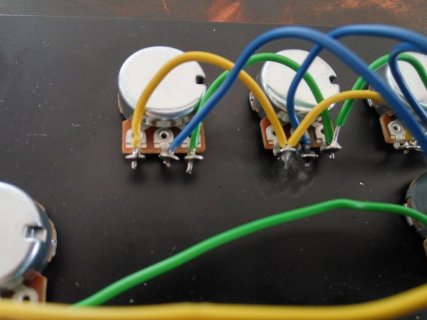
Guys, i have not figured out how to make this controller work yet. I think its the best idea if i explain in detail how i build it and maybe you more experienced guys can tell me if there is any fundamental mistake i made:

First of all, i screwed the 10k linear pots onto an eloxated aluminum plate and wired everything together like so:
13091665_1177756205568841_1464892077_o.jpg

The green wire is for my ground, the yellow wire is my power supply, and the blue wires are my "signals" that are connected to the analog input pins on the teensy.
The yellow wire was originally soldered to the 3,3V pin, but that had the same problem with jumping CC Values, so i switched the VIN pin (which is wrong from what I've heard) and still my CC Values are jumping.
The green wire is attached to the GND pin right besides the micro usb input. Is it maybe that i have to switch the green and yellow wires connections, that the green wire goes to the 3,3V pin and the yellow to GND ?

There are 3 blue wires soldered onto the pads on the bottom (A13, 28,26), whereas the other wires are just soldered to the side of the board. no soldering on the board is touching another wire or anything, it all looks pretty clean.

As live mentioned before, i used the code that recommended on the PJRC website and only changed the number of analog inputs. Again: The analog inputs are not really in the right order, but i don't know if thats a problem.
the pins i used are actually not a A0-A15, but A0, A1 , A2, A3, A4, A5, A6, A7, A8, A9, A10, A11, A13, A14, A15, A17
 
Last edited:
Guys, sorry for taking your time. i figured it out. the problem will make you laugh: i accidentally soldered the wires to the digital pins on the other side of the board and not the analog inputs.

I guess the next time i solder, i'll make sure im rested enough. Lol.
 
Yikes - that is even shown in your picture! Adrian and I wondered about your INDEX values swapping the read source - but didn't look at your soldering. And the board is labeled on the bottom too - that's okay my test sketch above hacked from your code was messed up too as written.
 
ooooh. Hopefully you are getting somewhere ... you will need to change your sketch if you have not wired numerically 'straight through' ... use a pin table array as your index!

global ...

Code:
int pintable [] ={A0, A1 , A2, A3, A4, A5, A6, A7, A8, A9, A10, A11, A13, A14, A15, A17};

and replace in your original sketch.....

Code:
// read current value at i-th input
    inputAnalog[i] = analogRead(pintable[i]);

If that doesn't work, I need better glasses. or the pintable members aren't ints or something to do with c++

or the freaking wiring!! :D
 
Last edited:
I actually think the USB MIDI page is pretty good. Maybe a bit of friendly advice (use 3.3V ...10k linear pot .. Aground .... maybe a smoothing cap .... possibly averaging and maybe internal resolution ...AND CHECK YOUR SOLDERING!!!:D ... pin numbering, maybe even pin registers (I use register reads myself)).

But most of this is actually already accessible on pjrc or in the forum. The basic tutorials as to 1 pot / switch are just excellent and maybe they should be linked to, as well as a 'how to solder' type site

Also, maybe something about USB midi device vs USB midi host ...

The awesome usb midi implementation of teensy is just a major selling point to my mind. It makes soo much possible for the DIY handyperson ... so, thanks for making that available to the great unwashed.

OH ... am I volunteering?? [takes step backwards] ... I have a multiswitch / rotary / motorised fader type project I'm finishing up (by the end of May ... waiting for an extender board for the bottom teensy pins).... the code works (ish) ... but there are lots of really good projects out there using multiple buttons and things ... I indend to 'publish' when I finish ... documenting the midi implementation and wiring even for 3 x 20 inputs is a bit of a fag, but I'll get there.
 
Thank you all so much for you help so far!

I got (almost) everything working on my midi controller, but Pin A13 does not work and i don't know why. everything is soldered correctly and most important, all the other pots work fine.
This is not really a big deal, but i want to "exclude" this pot from all the others, because it disturbs the signal when im using Ableton (it always switches to the pot 13). With which code can i exclude the controller from all the others ?
 
Another Problem is that everything works for a couple of seconds and then suddenly it stops working. When i pull out the usb cable and then put it in again, it works again, but only for a few seconds. It seems like the whole controller switches off, because it does not send any midi data.

There are 2 Pots that don't receive a signal, but only A13 doesn't work. There is a pot that sends signals to A1 and A15 at the same time and another one that sends to A3 and A17 (which i didn't even use) ..
 
Last edited:
I'd slow down the code temporarily, so that all the pots are read and data transmitted only once a second (put a delay(1000) in the loop() code). Then I'd use a midi sniffer on the computer to see what data bytes are exactly transmitted and when the teensy actually hangs up. At the same time I would (while the Teensy has not yet hung up) check the analog inputs with a multimeter or an oscilloscope and check if the transmitted data corresponds well to the measured values.

Another way is to temporarily modify the code, so that only one potentiometer is read and the data sent at a time. That would allow to check the wiring one by one.

There are chances that the teensy will not hang up in that slow mode. In that case, we might conclude that you are trying to transmit more data that the midi UART @31250baud can handle. Normally, to each transmitted byte, a stop bit is added, so that physically 9bits are sent. Dividing 31250 by 9 tells us that the maximum number of bytes which can be transmitted within 1 second are 3472. Each midi control change message consists of 4 bytes, thus a maximum of 868 messages can be sent in 1 second. Each loop() turn is prone to send up to 16 messages, thus not more than 54 should occur per second. This results in a minimum of delay(18) in the loop() to prevent an UART buffer overflow.

If you see that the "slow motion" mode with delay(1000) works well, reduce the delay value by small decrements until you find the optimal delay value (but still >= 18) which will make run your code the quickest possible without overloading the serial output.
 
Last edited:
Having A1 and A15 or A3 and A17 read synchronously, may be caused by ambiguous pin mapping. A digital pin is always addressed by #, while an analog pin should be addressed by A#. Thus, you should really add the printable array modification suggested by adrian above.
 
Status
Not open for further replies.
Back
Top