Serial1.available() seems to fail when first byte is NULL

Status
Not open for further replies.
im totaly out of ideas

I can on my trealterm see the teensy sending correct value on its serial port
I can see the MAX485 doing its work since the senix sensor connected to the MAX485 recieves the command and do its thing.
I can see the MAX485 converts back to rs232 since the realterm serial is connected to the rs232 side of the MAX485, the data is there
WHY WHY WHY cant the teensy see it correct.

Have you verified the data really is arriving correctly at Teensy's RX1 pin? For example, you could connect another MAX485 (with the driver always enabled) or RS232 chip to transmit the TTL-level signal that's actually at the RX1 pin.

i can only conclude its something with the teensy serial libraries that have a bug.

Well that's a pretty quick conclusion!

There may indeed be a bug in Serial1. If there is, certainly there must be a way to reproduce it by looping TX1 to RX1, or using another Teensy TX1 to transmit data to RX1. I can and will fix any bug, but first we need to find a way to reproduce it without your custom hardware and other device, which I do not have here.
 
As i tried to explain beeing non native english speaker. Everything is verified.

Data from Teensy TX1 pin is sent, i "sniff" it on RS232 side its there. MAX485 converts it correctly, the Senix sensor recieves it correct I can hear and see this on the sensor. It uses modbus so if it does en not recieve EXACT correct data it will not do anything..
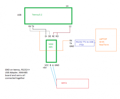
The response from the Senix sensor is sent to the MAX485 witch converts it correct. I verify this by hooking up my laptops serialport RX pin to the teensy RX1 pin the data is there, all the bytes every time i send data from teensy to trigger Senix sensor and get a reply.

Teensy via Serial1.avail.... show 1 or 2 or 6 or 8 there is ALWAYS 8 bytes on the RX1 pin. my laptops serial ports RX is hooked up together with teensy RX1 and everytime i see the bytes.

See picture trx1.png
 
If this really is a bug in Serial1, certainly there must be a way to reproduce it by looping TX1 to RX1, or using a 2nd Teensy to send the 8 bytes.

The response from the Senix sensor is sent to the MAX485 witch converts it correct. I verify this by hooking up my laptops serialport RX pin to the teensy RX1 pin the data is there

Are you connecting to the RS485 lines, or are you really truly connecting another listen-only path directly to the RX1 pin?

If you are monitoring the RS485 wires, you will not notice if the RX1 pin really has correct data. A timing error or other problem the RE/DE control signal or some other hardware problem is very likely the cause of this problem.

The software and hardware simply do not handle 0x00 differently than the other 255 possible bytes. I know you are convinced this is a software problem. It might be. But I am skeptical. If this really is a software problem, then there must be a way to reproduce it with another Teensy sending the 8 bytes. I will investigate and fix when such a test case is found. But I will NOT dig into the software while the only way to recreate the problem is your custom built RS485 hardware. For a software bug, we must first find a program than can run on this Teensy or a 2nd Teensy, to send the 8 or 9 bytes. Is that clear?
 
My "listner" is on the RX1 pin of the teensy, its NOT on the RS485 side

Im trying to set upp so my teensy talks from Serial1 to Serial2 via 2 identical rs232/485 converters

Will hard-wire them so one is always send and other is always recieve
 
Code:
void setup() {
 Serial1.begin(115200);
 Serial2.begin(115200);
 Serial.begin(115200);
 
}

void loop() {

  //Serial1.println("TESTprintfromSerial1");
  byte message2[] = {0x02, 0x03, 0x02, 0x08, 0x00, 0x01, 0x04, 0x43};
  //Serial1.flush();
  Serial1.write(message2, sizeof(message2));

  if (Serial2.available()) {
    while(Serial2.available()) {
      Serial.write(Serial2.read());
    }
  }

  delay(1000);

  }
t2.PNG

Left is the data Serial.write produces when reading from Serial2
Right is the data my "sniffer" in paralell with Serial2 RX pin produce

Its identical. and its 100% correct

I will try sending from Serial2 to serial1 now
 
Works from Serial2 to Serial1 aswell

Will now try to do it not hard wired, instead use the Serial1.transmitterEnable(Pin);
 
Code:
void setup() {
 Serial1.begin(115200);
 Serial2.begin(115200);
 Serial.begin(115200);

 Serial1.transmitterEnable(12);   //Serial1
 
}

void loop() {

  //Serial1.println("TESTprintfromSerial1");
  byte message2[] = {0x02, 0x03, 0x02, 0x08, 0x00, 0x01, 0x04, 0x43};
  //Serial1.flush();
  Serial2.write(message2, sizeof(message2));

  if (Serial1.available()) {
    while(Serial1.available()) {
      Serial.write(Serial1.read());
    }
  }

  delay(1000);

  }

this code works aswell as hardware, I recieve the data expected

If i add Serial2.transmitterEnable(14); // Serial2
It stops working, I was under the impression Serial1.transmitterEnable(12); handles the enabling/disabling of SEND/Recieve mode?
 
I also see, if i use BOTH
Serial1.transmitterEnable(12); // Serial1
Serial2.transmitterEnable(14); // Serial2

The data sent from Serial1 gets a NULL attached at the end, any idea why ?
If I only do Serial1.transmitterEnable(12); // Serial1 and not enable for Serial2 data is as it should be
 
Noticed,

as it is i get Serial1.avail..... reporting 1 2 6 or 8
if i put a pull down resistor on RX1 (2K2) i get 5 or 7..........
 
The data sent from Serial1 gets a NULL attached at the end, any idea why ?

Is that with the code on msg #32? How are the RX1, TX1, RX2 and TX2 pins connected? (and I'm also answering many questions and working on several projects.... so I can't devote a lot of time to trying to guess when messages are not very clear)

Please remember, I can't see how you are connecting the wires and running these tests.
 
Rx1 and tx1 connected to the rs485 converters rs232 side. Same with tx2 and rx2, connected to its own 485 converters rs232 side.

The 485 sides connected together.

Serial 1 and 2 can talk just fine with each other with the two max485 modules between when I hard wire di to pins.
Also if I only do Serial1.transmitterEnable(12) but not for serial2.
If I Serial2.transmitterEnable(14) a null gets added.

Seems teensy serial1 and 2 can talk to each other just fine with 2 max485 boards when I handle transmit / receive mode by hand.

Seems teensy serial converted via my max485 can send data flawles.
Seems the max485 converter converts incoming to Rx pin OK, based on that I read it perfectly with my PC serial port Rx pin wired together with teensy rx1.

Teensy rx1 reports incorrect bytes.

I'm totally out if ideas .

Serial1 talks to serial2 over the rs485.
But as soon as my senix sensor takes serial2 place . serial1 Rx don't "see" the bytes sent as they truly comes.
 
I have ordered several new other brand max485 converter boards .
I'm hoping the once I have is the problem . although hard to make that conclusion. But I will test
 
Maybe some fresh eyes... Are we mainly talking about this function?
Code:
void qSenix() {
  senixX = "";
  byte data[] {0x01, 0x01, 0x01, 0x01, 0x01, 0x01, 0x01, 0x01};
  unsigned long maxserialdly=300;  // the time we need to wait
  unsigned long previousMillis=millis(); // millis() returns an unsigned long.
  byte message2[] = {0x02, 0x03, 0x02, 0x08, 0x00, 0x01, 0x04, 0x43};
  Serial1.write(message2, sizeof(message2));
    int i = 0;
    Serial.print("Serial1.available()=");
    Serial.println(Serial1.available());
    while (Serial1.available()) {
      data[i] = Serial1.read();
      i++;
    }
I am not quite sure how you expect this to work?
So you tell the system to write 8 bytes out on Serial1. If we are talking about lets say 9600 baud, this will take a minimum of something like 8ms to output your data, before the system will then switch the RS485 into receive mode. During which time your program can run quite a bit of code.
So I would expect that Serial1.available(), should return 0 most of the time. Actually it may depend on if your input queue had data in it before your call to Senix().

Now if you want your code to wait for the complete message before returning, at a minimum I would probably do things like:
Serial1.clear(); - I believe this will clear out the receive buffer.

Would add the Serial1.flush() after the write. This will cause the code to wait until your write completes. But this still won't get you there, as it will take it near a ms to receive each character, which again your code will likely out pace the receiving of data. So you can wait in timed loop to receive the data. You could choose to keep a state table and each time your main loop calls this function it could see if more of the data is available...

Or you could try using some of the Arduino timed reads like Serial.readBytes(... ) If known size of message or maybe readBytesUntil or readString...
 
Ok, I am willing to wire this up here and run the test. I have very limited engineering time on this and *many* projects.

Several details are unclear. If I connect things differently and the problem does not occur, I probably will not repeat this test. So it is very important that you clearly specify exactly how I am supposed to connect the hardware.

Rx1 and tx1 connected to the rs485 converters rs232 side. Same with tx2 and rx2, connected to its own 485 converters rs232 side.

The 485 sides connected together.

Your text says "rs232 side", which I do not understand. You said you are using these modules. I do not see "rs232" anywhere on that page.

Those modules have 8 pins, called DI, DE, RE, R0, VCC, B, A, GND. I will use a similar chip and the same resistors. But I need you to say EXACTLY how all 8 pins are to be connected. Please, be extremely precise. Or post a diagram or schematic.

If anything is unclear, I may test a different hardware configuration that does not reproduce the problem. I do not intend to repeat this test multiple times if the error does not occur, so it is critically important that you tell me exactly how you have connected these modules. Do not leave any detail, even VCC and GND to guesswork.

If I Serial2.transmitterEnable(14) a null gets added.

Again, I need to point out your code in message #30 and #32 does not contain this line.

Please understand I have many questions to answer every day. I maintain all the Teensy code and many other libraries. I am working on many projects. I will also spend time to connect this circuit here on a breadboard and I will run the code you post.

But I WILL NOT RETRY IF YOUR CODE AND WIRING DOES NOT REPRODUCE THE PROBLEM.
 
Look, I really do want to help here. If you follow this forum, you'll see I do indeed spend time wiring up real hardware to actually test for problems people report.

If you've read this forum much, you've probably also seen many cases where I went to quite a lot of work to do this, but the problem wasn't reproducible. It's almost always some small detail, like differences in how those other signals like DE & RE are wired. Or power, or ground, or lots of other things where I just assume it's done the normal way I understand.

I know we're working with a language barrier here. I know you have limited time too. I do want to help, so please, post a very clear diagram or connection list for me to follow, so I get the hardware connected the same way you are testing. Please post a complete program, which is the one and only program I need to run to see the problem.

Please DO NOT make me try to use a program from earlier, with several edits you have mentioned. Please do not make me have to guess and fill in wiring details, like connecting DE & RE both to pin 12 or 14. Tell me exactly what steps to follow, and imagine I have many other people asking me to solve other problems, so I need it in a clear single message.

I will investigate this problem. Please help me to help find the solution for you.
 
Paul,

As I mentioned in post #39, I believe he has a coding timing problem. Maybe I am wrong, but:
He does a Serial1.write of 8 bytes, immediately followed by a Serial1.available(). So there has not been any time elapsed to actually send the data out over the hardware port, let alone time for the hardware on the other side to receive it and send a response for us to read in.
 
Yeah, that part in the code doesn't make much sense.

I'm not completely ruling out a software bug in the serial code. But I have personally verified the driver enable with real RS485 usage and by watching on my scope, and I've personally verified reception of 0x00 bytes... so if there is a bug here, it's something very elusive. That's why I'm so insistent on a clear test.
 
KurtE, look at the first post, I describes several delays used to see "when" data arrives after the sending of data from teensy.

But it is alot of code examples and descriptions around. I will post current code and a connection diagram as soon as I can. And all other requested information
We are on different time zones.
 
The code used
Code:
#define SSerialTxControl 12   //RS485 Direction control
#define RS485Transmit    HIGH
#define RS485Receive     LOW

#define Pin13LED         13

String senixX = "";


void setup() {
  // put your setup code here, to run once:
  Serial.begin(9600);
  Serial1.begin(115200);
  
  Serial.println("BOOTING!");

  pinMode(Pin13LED, OUTPUT);   
  pinMode(SSerialTxControl, OUTPUT);
  
  //Serial1.transmitterEnable(12);

  digitalWrite(SSerialTxControl, RS485Receive);
  delay(10);
}

void loop() {
  // put your main code here, to run repeatedly:
  Serial.println("Start loop");
  qSenix();
  Serial.println(senixX);
  delay(3000);

}

void qSenix() {
  senixX = "";
  byte data[] {0x01, 0x01, 0x01, 0x01, 0x01, 0x01, 0x01, 0x01};
  unsigned long maxserialdly=300;  // the time we need to wait
  unsigned long previousMillis=millis(); // millis() returns an unsigned long.
  Serial1.flush();
  digitalWrite(SSerialTxControl, RS485Transmit);  // Enable RS485 Transmit
  //  Serial1.flush();
  //byte message1[] = {0x01, 0x03, 0x02, 0x08, 0x00, 0x01, 0x04, 0x70};
  //Serial1.write(message1, sizeof(message1));
  //byte message3[] = {0x03, 0x03, 0x02, 0x08, 0x00, 0x01, 0x05, 0x92};
  byte message2[] = {0x02, 0x03, 0x02, 0x08, 0x00, 0x01, 0x04, 0x43};
  Serial1.flush();
  Serial1.write(message2, sizeof(message2));
  Serial1.flush();
  delay(15);  // small delay to make sure all data sent before togling RS485 Transmit to recieve
  digitalWrite(SSerialTxControl, RS485Receive);  // Disable RS485 Transmit
  //byte temp = Serial1.read();
  delay(15);   // Small delay to make sure all data sent from senix sensor have been sent before trying to read all. at 115200baud this way more then enough time.
 
  //while(!Serial1.available() && (unsigned long)(millis() - previousMillis) < maxserialdly) ;
  //while(!Serial1.available() && (unsigned long)(millis() - previousMillis) < maxserialdly) ;
    
    int i = 0;
    Serial.print("Serial1.available()=");
    Serial.println(Serial1.available());
    while (Serial1.available()) {
      // get the new byte:
      //char inChar = (char)Serial1.read();
      //Serial.println(inChar);
      //senixX += inChar;
      //Serial.println(i);
      data[i] = Serial1.read();
      i++;
    }

  Serial.println("-");
  Serial.println(data[0], BYTE);
  Serial.println(data[1], BYTE);
  Serial.println(data[2], BYTE);
  Serial.println(data[3], BYTE);
  Serial.println(data[4], BYTE);
  Serial.println(data[5], BYTE);
  Serial.println(data[6], BYTE);
  Serial.println(data[7], BYTE);
  Serial.println("-");
 
  /*
  byte message2[] = {0x02, 0x03, 0x02, 0x08, 0x00, 0x01, 0x04, 0x43};
  Serial1.write(message2, sizeof(message2));
  delay(10);
  
  byte message3[] = {0x03, 0x03, 0x02, 0x08, 0x00, 0x01, 0x05, 0x92};
  Serial1.write(message3, sizeof(message3));
  */  
 
}

The schema
sch.png

Flow
1. Teensy sends 0x02, 0x03, 0x02, 0x08, 0x00, 0x01, 0x04, 0x43
0x02, 0x03, 0x02, 0x08, 0x00, 0x01, 0x04, 0x43 is recieved by the senix sensor OK
2. Senix sensor sends back its data 0x02, 0x03, ............. CRC
Serial.println(Serial1.available()); reports any of 1,2,6 or 8. The byte array data[] 0 to 8 have incorrect data (the data that actualy are set)
the laptop running realterm connected to teensy RX1 via the rs232<>usb ftdi based converter prints out the correct data ever time.

Thats the wierd part. Serial.println(Serial1.available()); gives a random number 1,2,6,8 while i look at the data on my second screen and its correct.

I hope its understandable.

PS.
the DI DE RE RO all have 10K pull up resistors on the pcb
 
Last edited:
If I understand KurtE in post#42 the problem is the perhaps too short "delay(15);" in bold below after the send/flush.

The code used ...
Code:
...
void qSenix() {
...
  Serial1.write(message2, sizeof(message2));
  Serial1.flush();
  delay(15);  // small delay to make sure all data sent before togling RS485 Transmit to recieve
  digitalWrite(SSerialTxControl, RS485Receive);  // Disable RS485 Transmit
[B]  delay(15);   // Small delay to make sure all data sent from senix sensor have been sent before trying to read all. at 115200baud this way more then enough time.[/B] 

    int i = 0;
    Serial.print("Serial1.available()=");
    Serial.println(Serial1.available());
    while (Serial1.available()) {
...
}
...

Thats the wierd part. Serial.println(Serial1.available()); gives a random number 1,2,6,8 while i look at the data on my second screen and its correct.

This isn't random but a RACE condition where you are looking at .available() while the RETURN bytes are still in transmission. That is accurately showing the number of bytes received at that time.

Since you have variable " i " counting the bytes received - please print that on exiting the while( .available ){} loop.

Make that delay(15) more like delay(50) or more until the Serial.println(Serial1.available()); gives 8 if you want to see the number before you start pulling out the data.

If you do that update your code above and perhaps add a copy of the USB output from Teensy as you see it for clarity.
 
delay(15) i have tried 20, 50, 100, 200, 300, 400,500
Same result. a quick googling indicates sending 32bytes take 3.33ms at 115200 baud. so my 8bytes sends in less then 1ms, 15ms should be more then enough.

In my example, even with "only" 15ms delay, the RETURN bytes should not be in transmission. Should already be transmitted and in teensy uart buffer long before 15ms have passed.
If 15ms is to short, as mentioned above, i tried delays up to 500ms.

the counter 'i' if printed after while loop exits shows 1, 2, 6, 8. same as the output from Serial1.available()); as expected

I have to wait untill evening to be able to get the output from teensy usb serial.
 
Last edited:
Thanks - that answers that question. This comment led me to understand it was all showing up in the end: "while i look at the data on my second screen and its correct" (since I couldn't see what screen you were looking at).

Question: Is there any chance you are dropping the "digitalWrite(SSerialTxControl, RS485Receive); // Disable RS485 Transmit" after the remote device has already tried to transmit given the delay(15) before that? I'm not sure if the other device gets a signal when that is done - or if it just blasts out ASAP. If my math is agreeable - indeed 64 bits at 115K/bps only takes one 1,800th of a second - or under 0.6 ms? So after .flush() that be delay(1); ?
 
The digitalWrite(SSerialTxControl, RS485Receive); is dropped correctly i would gues since my Laptop with the realterm connected in paralell with teensy RX1 do recieve all the bytes

This is whats anoying. I can see with other equipment then the teensy, in my case my laptop with realterm reading the RX1 pin of the teensy. The data IS there.
It pops up on my realterm loop after loop after loop. Yet Teensy do not "see" it correct,

im going insane.
 
Status
Not open for further replies.
Back
Top