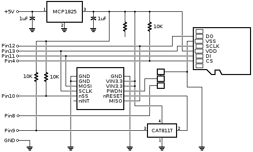
Is there a schematic for the WIZ820io adapter Rev2? On this page https://www.pjrc.com/store/wiz820_sd_adaptor.html in the Electrical Connections table the WIZ820io RESET is shown connected to Teensy D9. This is true on adapter Rev1 but seems not to be the case on Rev2, as beeped with a meter. Rather D9 goes to one corner of the new reset chip, which might be its input trigger or a wire-or output. What is that part number? It is labeled VEAH but I could not google an answer. A schematic for this board would be helpful. I just bought four and am trying to add them to an existing system and need to understand the function of all signals. I'll be using this with the WIZ820io to start and then switching to the new WIZ850io ASAP.
Minimum reset low time for the WIZ820io/W5200 is 2 usec. For the WIZ850io/W5500 it is 500 usec. I wonder what the min reset pulse spec for the VEAH reset chip is, and what its threshold voltage is.
Thanks
Bruce
Minimum reset low time for the WIZ820io/W5200 is 2 usec. For the WIZ850io/W5500 it is 500 usec. I wonder what the min reset pulse spec for the VEAH reset chip is, and what its threshold voltage is.
Thanks
Bruce