SPI Returns Zero with IMU Sensor on Teensy 3.2

Status
Not open for further replies.
Only pullups I've seen are on the CS lines to make sure no sharing devices 'float' into an active transmission for another device. I just saw this myself having a touch display where I didn't start the software on the Touch part of the display unit and the T_CS pin wasn't held high so it corrupted the display data on the shared data lines.

By CS lines you mean the Slave Select lines?

Any precautions related to the breadboard itself for both SPI and I2C? Do breadboard models make a difference? Jumper cables (solid vs. stranded)? Thanks.
 
I tried the pull-ups, but no luck.

Something is just not right with the SPI reads.

I'd be happy to donate a pair of Sparkfun LSM6DS3 6-dof IMU breakout boards and the wire harness I used to PRJC to see if they can get it to work for the community and Teensy users who want to use SPI for similar devices over long distances (~3 feet).
 
Okay, I implemented I2C for the IMU device on the Teensy 3.2 as a check using my own I2C read/write functions and the Sparkfun library. The Sparkfun functions worked on the Arduino Due with I2C, so I know it works, however with too many dropouts, which is one of the main reasons I purchased the Teensy board.

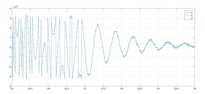
Setting the same registers as on the Due (accel limits: +/- 8g, gyro limits: +/- 1,000 deg/sec), there is a problem on the Teensy 3.2. It appears that the accel and gyro output registers (16-bit word read in an 8-bit pair) are mangled. As a demo, I lightly moved the IMU suspended from the CAT5 cable and the response almost fills the limits of the gyro, and the peaks seem to fold over themselves. I enclosed a plot showing this.

This issue happens whether I use my I2C functions or the Sparkfun library. I made sure to put in 4.7K pull-ups on the SDA and CLK lines. And I made sure to use "int16_t" when merging the 8-bit pairs that make up the 16-bit gyro output:

out3 = (int16_t)out1 | int16_t(out2 << 8);

Appreciate your help on this. Thanks.

gyro_i2c.jpg
 
Last edited:
Yikes, SPI over 3 feet of wire! That's a mighty long distance, even for I2C.

That data problem looks like the typical 16 to 32 bit sign extension problem. You didn't post the complete code (eg, the Forum Rule) and the 1 line you did post doesn't even look like correct C syntax. Very hard to help resolve a code problem without the actual code...

This type of problem often involves subtle issues which depend on the declared types for the variables, so it really is essential to see the whole program with the variables types defined, not just the lines with the expression.
 
Okay, I found the problem with my I2C readings. Each accel and gyro reading from the LSM6DS3 IMU is expressed as a 16-bit word in two’s complement. The problem: the Wire.receive() function is incorrectly reading the second 8-bit word - it's simply copying the first 8-bit word. My I2C read function is shown below. Separately, the Sparkfun library yields the same problem - this was not a problem on the Arduino Due.

Code:
int16_t  i2c_read_16bit( uint8_t target)
{
    uint8_t   nbyte = 2;
    uint8_t   out1, out2;
    int16_t   out3;

    Wire.beginTransmission(I2C_ADDR);
    Wire.write(target);
    Wire.endTransmission();
    
    Wire.requestFrom(I2C_ADDR, (byte)2);

    while (Wire.available() < 2);
            
    out1 = Wire.receive();
    out2 = Wire.receive();

    out3 = (int16_t)out1 | int16_t(out2 << 8);
    
    sprintf(nmeacx, "  %d %d %d \r\n",  out1, out2, out3);
    Serial.print(nmeacx);
       
    return  out3;
}

Here's a few lines of output - as you can see, the 2nd column equals the 1st:

Code:
  206 206 -12594 
  84 84 21588 
  218 218 -9510 
  245 245 -2571 
  235 235 -5141 
  197 197 -14907 
  211 211 -11309 
  81 81 20817 
  216 216 -10024 
  4 4 1028 
  240 240 -3856 
  193 193 -15935 
  207 207 -12337 
  86 86 22102 
  222 222 -8482 
  251 251 -1029

The first 8-bit word is the least-significant-byte. The next 8-bit word is the most-significant-byte. The bug causes the LSB to be left-shifted by 8 bits (a factor of 2^8). This explains why my gyro readings are so high and mangled.

The Wire.h library on the Teensy 3.2 seems to work fine provided that only 8 bits are read at a time.

Hopefully this problem is not caused by my 3-foot long CAT5 cable. I need this for the very large bot.
 
Last edited:
I couldn't help but notice every line printed has the exact same number for out1 and out2. That seems very unlikely to be real data from your sensor.

Perhaps this line is the problem?

Code:
while (Wire.available() < 2);

Maybe try structuring your code similarly to the example in File > Examples > Wire > master_reader.
 
I couldn't help but notice every line printed has the exact same number for out1 and out2. That seems very unlikely to be real data from your sensor.

That's my point in reply #31 - out2 (which is the MSB) is incorrectly matching out1 (LSB).

Has anyone read a 16-bit result in two's complement on the Teensy 3.2 with I2C?


Perhaps this line is the problem?

while (Wire.available() < 2);

Maybe try structuring your code similarly to the example in File > Examples > Wire > master_reader.


I'm at work at the moment and don't have access to the Arduino IDE, but I can say I tried many variations with the same incorrect results. The approach in reply #31 is based on the Adafruit library, which works properly on the Arduino Due. I also tried the Sparkfun library (link below) but same error - however it does work on the Arduino Due.

https://github.com/sparkfun/SparkFun_LSM6DS3_Arduino_Library/tree/master/src

Key excerpt from Sparkfun library:

Code:
status_t LSM6DS3Core::readRegisterRegion(uint8_t *outputPointer , uint8_t offset, uint8_t length)
{
	status_t returnError = IMU_SUCCESS;

	//define pointer that will point to the external space
	uint8_t i = 0;
	uint8_t c = 0;
	uint8_t tempFFCounter = 0;

	switch (commInterface) {

	case I2C_MODE:
		Wire.beginTransmission(I2CAddress);
		Wire.write(offset);
		if( Wire.endTransmission() != 0 )
		{
			returnError = IMU_HW_ERROR;
		}
		else  //OK, all worked, keep going
		{
			// request <length> bytes from slave device
			Wire.requestFrom(I2CAddress, length);
			while ( (Wire.available()) && (i < length))  // slave may send less than requested
			{
				c = Wire.read(); // receive a byte as character
				*outputPointer = c;
				outputPointer++;
				i++;
			}
		}
		break;

	case SPI_MODE:
		// take the chip select low to select the device:
		digitalWrite(chipSelectPin, LOW);
		// send the device the register you want to read:
		SPI.transfer(offset | 0x80);  //Ored with "read request" bit
		while ( i < length ) // slave may send less than requested
		{
			c = SPI.transfer(0x00); // receive a byte as character
			if( c == 0xFF )
			{
				//May have problem
				tempFFCounter++;
			}
			*outputPointer = c;
			outputPointer++;
			i++;
		}
		if( tempFFCounter == i )
		{
			//Ok, we've recieved all ones, report
			returnError = IMU_ALL_ONES_WARNING;
		}
		// take the chip select high to de-select:
		digitalWrite(chipSelectPin, HIGH);
		break;

	default:
		break;
	}

	return returnError;
}
 
Last edited:
I couldn't help but notice every line printed has the exact same number for out1 and out2. That seems very unlikely to be real data from your sensor.

That's my point in reply #31. out2 (which is the MSB) is incorrectly matching out1 (LSB).

Has anyone read a 16-bit result in two's complement on the Teensy 3.2 with I2C?


Perhaps this line is the problem?

while (Wire.available() < 2);

Maybe try structuring your code similarly to the example in File > Examples > Wire > master_reader.

Okay, I tried the master_reader example. But no luck, out2 still incorrectly matches out1. Code below:

Code:
uint16_t  i2c_read_16bit( uint8_t target)
{
    char     out1, out2;
    int16_t  out3;

    Wire.beginTransmission(I2C_ADDR);
    Wire.write(target);
    Wire.endTransmission();
    
    Wire.requestFrom(I2C_ADDR, 2);     // request 2 bytes from slave device #8
            
    while ( Wire.available() )
    {
        out1 = Wire.read();
        out2 = Wire.read();
    }

    out3 = (int16_t)out1 | int16_t(out2 << 8);
    
     sprintf(nmeacx, "  %d %d %d \r\n",  (int16_t)out1, (int16_t)out2, out3 );
     Serial.print(nmeacx);
       
    return  out3;
}

I also tried putting in a delay between out1 and out2, but no luck.

The approach in reply #31 is based on the Adafruit library, which works properly on the Arduino Due. The Sparkfun library also works on the Due, but not on the Teensy 3.2 - same out2=out1 error..

https://github.com/sparkfun/SparkFun_LSM6DS3_Arduino_Library/tree/master/src

Excerpt from Sparkfun library:

Code:
status_t LSM6DS3Core::readRegisterRegion(uint8_t *outputPointer , uint8_t offset, uint8_t length)
{
	status_t returnError = IMU_SUCCESS;

	//define pointer that will point to the external space
	uint8_t i = 0;
	uint8_t c = 0;
	uint8_t tempFFCounter = 0;

	switch (commInterface) {

	case I2C_MODE:
		Wire.beginTransmission(I2CAddress);
		Wire.write(offset);
		if( Wire.endTransmission() != 0 )
		{
			returnError = IMU_HW_ERROR;
		}
		else  //OK, all worked, keep going
		{
			// request <length> bytes from slave device
			Wire.requestFrom(I2CAddress, length);
			while ( (Wire.available()) && (i < length))  // slave may send less than requested
			{
				c = Wire.read(); // receive a byte as character
				*outputPointer = c;
				outputPointer++;
				i++;
			}
		}
		break;

	case SPI_MODE:
		// take the chip select low to select the device:
		digitalWrite(chipSelectPin, LOW);
		// send the device the register you want to read:
		SPI.transfer(offset | 0x80);  //Ored with "read request" bit
		while ( i < length ) // slave may send less than requested
		{
			c = SPI.transfer(0x00); // receive a byte as character
			if( c == 0xFF )
			{
				//May have problem
				tempFFCounter++;
			}
			*outputPointer = c;
			outputPointer++;
			i++;
		}
		if( tempFFCounter == i )
		{
			//Ok, we've recieved all ones, report
			returnError = IMU_ALL_ONES_WARNING;
		}
		// take the chip select high to de-select:
		digitalWrite(chipSelectPin, HIGH);
		break;

	default:
		break;
	}

	return returnError;
}
 
Code:
    while ( Wire.available() )
    {
        out1 = Wire.read();
        out2 = Wire.read();
    }

This doesn't look quite like the master_reader example, which reads once per loop.

Code:
  while(Wire.available())    // slave may send less than requested
  { 
    char c = Wire.read(); // receive a byte as character
    Serial.print(c);         // print the character
  }
 
Last edited:
This doesn't look quite like the master_reader example, which reads once per loop.

Code:
  while(Wire.available())    // slave may send less than requested
  { 
    char c = Wire.read(); // receive a byte as character
    Serial.print(c);         // print the character
  }


Okay, I constructed the function per the example in File > Examples > Wire > master_reader. Here's my I2C read function:

Code:
void  i2c_read_16bit( uint8_t target)
{
    Wire.beginTransmission(I2C_ADDR);
    Wire.write(target);
    Wire.endTransmission();
    
    Wire.requestFrom(I2C_ADDR, 2);  // request 2 bytes from slave device #8
            

    while(Wire.available())         // slave may send less than requested
    { 
        char c = Wire.read();       // receive a byte as character
        Serial.print((int16_t)c);   // print the character as an integer
        Serial.print(" ");          
    }

    Serial.println(" ");         
}

Same error as before - the 2nd byte incorrectly equals the 1st byte:

Code:
48 48  
43 43  
58 58  
96 96  
118 118  
154 154  
202 202  
3 3  
47 47  
52 52  
38 38  
252 252

Given that I also tried the Sparkfun library (excerpt in reply #35), which works on the Arduino Due with this LSM6DS3 IMU, could the problem be the Wire.h library on the Teensy 3.2? Has anyone read a 16-bit result in two's complement on the Teensy 3.2 with I2C? Thanks.


For completeness, here's my entire code demonstrating the problem:
Code:
#include <Wire.h>


// I2C Pins
#define   I2C_ADDR   0x6B
#define   SDAX       18
#define   SCLX       19


// IMU Chip Registers
uint8_t   address_accelx_lsb = 0X28;
uint8_t   address_accely_lsb = 0X2A;
uint8_t   address_accelz_lsb = 0X2C;
uint8_t   address_gyrox_lsb  = 0X22;  
uint8_t   address_gyroy_lsb  = 0X24;
uint8_t   address_gyroz_lsb  = 0X26;


void  i2c_write( uint8_t target, uint8_t message)
{
    Wire.beginTransmission(I2C_ADDR);
    Wire.write(target);
    Wire.write(message);
    Wire.endTransmission();
}


uint8_t  i2c_read( uint8_t target)
{
    uint8_t   out;

    Wire.beginTransmission(I2C_ADDR);
    Wire.write(target);
    Wire.endTransmission();
    
    Wire.requestFrom(I2C_ADDR, 1);
    
    while ( Wire.available()<1 )    // slave may send less than requested
    {
        out  = Wire.receive();
    }
        
    return  out;
}


void  i2c_read_16bit( uint8_t target)
{
    Wire.beginTransmission(I2C_ADDR);
    Wire.write(target);
    Wire.endTransmission();
    
    Wire.requestFrom(I2C_ADDR, 2);  // request 2 bytes from slave device #8
            

    while(Wire.available())         // slave may send less than requested
    { 
        char c = Wire.read();       // receive a byte as character
        Serial.print((int16_t)c);   
        Serial.print(" ");           
    }

    Serial.println(" ");         
}


void init_imu()
{
    uint8_t   target, writeout;
    uint8_t   out1, out2;

    Wire.begin();

    
    target   = 0X12;
    writeout = 0X00;   // 00000000
    i2c_write( target, writeout);

    target   = 0X08;
    writeout = 0X09;   
    i2c_write( target, writeout);

    target   = 0X10;
    writeout = 0X4E;  // 0100 1110,  odr: 104Hz, +/-8g, filter: 100hz
    i2c_write( target, writeout);

    target   = 0X11;
    writeout = 0X48;  // 0100 1000,  odr: 104hz, 1000 dps
    i2c_write( target, writeout);
   
    target   = 0X13;
    writeout = 0X80;  // bandwidth determined by setting BW_XL[1:0]
    i2c_write( target, writeout);
}


void setup()
{
    Serial.begin(115200);  // INIT SERIAL
    
    init_imu();           // INIT ACCEL & GYRO REGISTERS

    delayMicroseconds(1000000);

    
    // STREAM GYRO
    for(int ii=0; ii<12; ii++)
    {
        i2c_read_16bit(address_gyrox_lsb);
        delayMicroseconds(10000);
    }

}


void loop()
{ 
}
 
Last edited:
Yes, many people have used motion sensors with 16 bit data over I2C. The sensors on the Prop Shield work this way too.

It's still possible, but unlikely there's a bug in the Wire library causing this problem on your project, but not impacting thousands of other uses with 16 bit I2C sensors.

Maybe it's time for me to take a closer look at this case?
 
You can't typecast a signed 8 bit value to a signed 16 bit value.
Well you can but 0xFF(-1) will become 0x00FF(127). Assuming Char is signed in this case which may not be true

If you're after a signed 16 bit value from a register you probably want the following:
Code:
int16_t i2c_read_16bitSigned(uint8_t target) {
    Wire.beginTransmission(I2C_ADDR);
    Wire.write(target);
    Wire.endTransmission();
    
    // request 2 bytes from slave device #8
    if (Wire.requestFrom(I2C_ADDR, 2, true) == 2) {
            
        uint8_t out1 = Wire.receive();
        uint8_t out2 = Wire.receive();

        int16_t out3 = (int16_t) ((out2 << 8) | out1); 

        return out3;
    }

    return 0; // If we don't receive 2 bytes, return 0


In your example you read register 0x22 twice and of course witness that the contents is the same. You need to read 0x22 and 0x23 and then combine the results
 
Last edited:
Ok, I've ordered this sensor from Sparkfun.

Regarding combining the two 8 bit bytes to a 16 bit signed integer, I can tell you with certainty this code for the Prop Shield absolutely does work on Teensy 3.2.

https://github.com/PaulStoffregen/NXPMotionSense/blob/master/NXPMotionSense.cpp#L149

But it really looks like something else is very wrong here. No matter how you combine bytes, you're never going to get the right answer if you're only getting the same byte duplicated rather than both actual bytes. Garbage in, garbage out...
 
But it really looks like something else is very wrong here. No matter how you combine bytes, you're never going to get the right answer if you're only getting the same byte duplicated rather than both actual bytes. Garbage in, garbage out...

See the following explanation:

In your example you read register 0x22 twice and of course witness that the contents is the same. You need to read 0x22 and 0x23 and then combine the results

Actually reading #31 I see this may not be true. The device does support multi-reading as described in Page 36. This does state however:
Each data transfer must be
terminated by the generation of a STOP (SP) condition

Because of this we must use:
Code:
Wire.requestFrom(address, quantity, TRUE) //address, quantity, stop
 
Last edited:
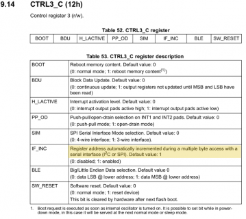
Looking at your code and the chip's datasheet, I see you're configuring IF_INC in CTRL3_C to zero.

Code:
    target   = 0X12;
    writeout = 0X00;   // 00000000
    i2c_write( target, writeout);

Maybe try setting this to 1, which is its default value.

sc.png
(click for full size)

Perhaps this could be the reason you're getting the same byte twice?
 
However, I still want to know why Sparkfun's library isn't working out-of-the-box. Can you please tell me exactly how you tested with their library? Their lib includes *many* examples. Which did you run? Did you make any edits? Please help me to exactly recreate the failure you saw when running Sparkfun's code.

When this sensor arrives, I would like to duplicate this result and get to the bottom of why it's not working with the library Sparkfun publishes.
 
Last edited:
You can't typecast a signed 8 bit value to a signed 16 bit value.
Well you can but 0xFF(-1) will become 0x00FF(127).

I'll take a look at your typecasting point. However, that will not change the error with out2 (MSB) equaling out1 (LSB).

In your example you read register 0x22 twice and of course witness that the contents is the same. You need to read 0x22 and 0x23 and then combine the results

The 0X22 contains a 16-bit gyro reading at an instant in time. You can in fact read 0x22 (LSB) followed by 0x23 (MSB), then merge them, but then you have a gyro reading from two separate instants in time. This may be a decent workaround for measuring low frequency events, but will not work for my application.

Because of this we must use:
Code:
Wire.requestFrom(address, quantity, TRUE) //address, quantity, stop
I tried this, but no luck.

Looking at your code and the chip's datasheet, I see you're configuring IF_INC in CTRL3_C to zero.
Maybe try setting this to 1, which is its default value.

I'll try that when I get home. I can say now that I'm using the same initialization registers & values used on my working Arduino Due project, including CTRL3_C. And I'll send my complete code demonstrating pieces of the Sparkfun library.

I also plan to try the alternate I2C library written by nox771.

Appreciate your help on this.
 
Last edited:
The 0X22 contains a 16-bit gyro reading at an instant in time. You can in fact read 0x22 (LSB) followed by 0x23 (MSB), then merge them, but then you have a gyro reading from two separate instants in time. This may be a decent workaround for measuring low frequency events, but will not work for my application

Did you try my example code?
You can't transfer more than one byte at a time. You can do multi-reading of bytes sure but you still have to have an acknowledgement between bytes. See Page 36
 
Looking at your code and the chip's datasheet, I see you're configuring IF_INC in CTRL3_C to zero.

Code:
    target   = 0X12;
    writeout = 0X00;   // 00000000
    i2c_write( target, writeout);

Maybe try setting this to 1, which is its default value.


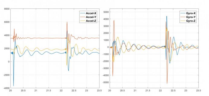
Wow, you solved the problem. Setting the "IF_INC" bit to 1 enables reading the full 16-bit gyro result in two's complement. When I lightly tap the IMU, I get good readings in all 3 accels and 3 gyros. Here's a time history plot (counts vs. time).

imu.jpg

Here's my full code. It includes a timer that loops the main function at a sample rate of 100hz.

Code:
#include <Wire.h>


//  TIMING
#define MAXSAMPLE 3000  // Number of data samples:
#define CLAW_FS   100   // Control System Sample Rate (Hz)
volatile boolean  PING      = false;

IntervalTimer     clawtimer;


// I2C Pins
#define   I2C_ADDR   0x6B
#define   SDAX       18
#define   SCLX       19


// IMU Chip Registers
uint8_t   address_accelx_lsb = 0X28;
uint8_t   address_accely_lsb = 0X2A;
uint8_t   address_accelz_lsb = 0X2C;
uint8_t   address_gyrox_lsb  = 0X22;  
uint8_t   address_gyroy_lsb  = 0X24;
uint8_t   address_gyroz_lsb  = 0X26;


// IMU COUNTS
int16_t   caccx, caccy, caccz, cgyrox, cgyroy, cgyroz;


// STREAM VARIABLES
#define MAXLINE 136
char  nmeac[MAXLINE];


void  i2c_write( uint8_t target, uint8_t message)
{
    Wire.beginTransmission(I2C_ADDR);
    Wire.write(target);
    Wire.write(message);
    Wire.endTransmission();
}


uint8_t  i2c_read( uint8_t target)
{
    uint8_t   out;

    Wire.beginTransmission(I2C_ADDR);
    Wire.write(target);
    Wire.endTransmission();
    
    Wire.requestFrom(I2C_ADDR, 1);
    
    while ( Wire.available()<1 )    // slave may send less than requested
    {
        out  = Wire.receive();
    }
        
    return  out;
}


int16_t  i2c_read_16bit( uint8_t target)
{
    byte     nbyte = 2;
    char     binx[2];
    int16_t  out;
    byte     ii;
    
    Wire.beginTransmission(I2C_ADDR);
    Wire.write(target);
    Wire.endTransmission();
    
    Wire.requestFrom(I2C_ADDR, nbyte, 1);  // request 2 bytes from slave device #8
            
    ii=0;
    while(Wire.available() && ii<nbyte)         // slave may send less than requested
    { 
        binx[ii] = Wire.read();       // receive a byte as character
        ii++;
    }

    out = (int16_t)(binx[0] | (binx[1] << 8));

    return out;
}


void init_imu()
{
    uint8_t   target, writeout;
    uint8_t   out1, out2;

    Wire.begin();

    
    target   = 0X12;
  //writeout = 0X00;   // DO NOT USE; PREVENTS READING 2ND BYTE OF 16B-BIT GYRO/ACCEL RESULT
    writeout = 0X04;   // 00000100
    i2c_write( target, writeout);

    target   = 0X08;
    writeout = 0X09;   
    i2c_write( target, writeout);

    target   = 0X10;
    writeout = 0X4E;  // 0100 1110,  odr: 104Hz, +/-8g, filter: 100hz
    i2c_write( target, writeout);

    target   = 0X11;
    writeout = 0X48;  // 0100 1000,  odr: 104hz, 1000 dps
    i2c_write( target, writeout);
   
    target   = 0X13;
    writeout = 0X80;  // bandwidth determined by setting BW_XL[1:0]
    i2c_write( target, writeout);
}


void beacon()
{
    PING = true;      
}


boolean wow()
{
    return PING;
}


//-------------------------------------------------------------
//                      MAIN PROGRAM
//-------------------------------------------------------------
void setup()
{
    long  ii, microsec;

    Serial.begin(115200);                 // INIT SERIAL
    
    init_imu();                           // INIT ACCEL & GYRO REGISTERS

    // TIMER SETUP
    microsec = 1.0/CLAW_FS*1e6;
    clawtimer.begin( beacon, microsec );  // INIT TIMER

    delayMicroseconds(1000000);

    ii=0;
    while (ii<MAXSAMPLE)
    {        
        // FORCE FIXED TIME STEP
        while ( wow()!=true);         
        PING  = false;

        // READ IMU - UNITS: COUNTS
        caccx  = i2c_read_16bit( address_accelx_lsb );
        caccy  = i2c_read_16bit( address_accely_lsb );
        caccz  = i2c_read_16bit( address_accelz_lsb );
        cgyrox = i2c_read_16bit( address_gyrox_lsb );
        cgyroy = i2c_read_16bit( address_gyroy_lsb );
        cgyroz = i2c_read_16bit( address_gyroz_lsb );


        sprintf(nmeac, "  %d %d %d %d %d %d \r\n",   
        caccx, caccy, caccz, cgyrox, cgyroy, cgyroz );

        Serial.print(nmeac); 

        ii++;
    }

}


void loop()
{ 
}


When this sensor arrives, I would like to duplicate this result and get to the bottom of why it's not working with the library Sparkfun publishes.

Hopefully the IMU hasn't shipped so you can cancel your order. Either way, I will purchase a couple more Teensy 3.2 boards and other products.

For now, the I2C functionality works. I do observe some occasional random dropouts nearing 255 counts above the noise floor - this might be related to typecasting. I still don't understand why the 16-bit gyro & accel readings have negative counts.

Overall, the Teensy 3.2 is an excellent alternative to the Arduino Due. Looking forward to the K66 board. Thanks very much for your help.
 
Last edited:
Sparkfun already shipped the sensor.

I still want to get to the bottom of why Sparkfun's library didn't work. Can you save me a little time by giving me precise info about what you tried with their library which didn't work on Teensy?
 
I still want to get to the bottom of why Sparkfun's library didn't work. Can you save me a little time by giving me precise info about what you tried with their library which didn't work on Teensy?

The functions I pulled from the Sparkfun library didn't work because the IF_INC bit in the CTRL3_C register was improperly set as detailed in reply #46. With the proper setting, it works. Complete example code below:

Code:
#include <Wire.h>


//  TIMING
#define MAXSAMPLE 3000  // Number of data samples:
#define CLAW_FS   100   // Control System Sample Rate (long) (Hz)
volatile boolean  PING      = false;

IntervalTimer     clawtimer;


// I2C Pins
#define   I2C_ADDR   0x6B
#define   SDAX       18
#define   SCLX       19


// IMU Chip Registers
uint8_t   address_accelx_lsb = 0X28;
uint8_t   address_accely_lsb = 0X2A;
uint8_t   address_accelz_lsb = 0X2C;
uint8_t   address_gyrox_lsb  = 0X22;  
uint8_t   address_gyroy_lsb  = 0X24;
uint8_t   address_gyroz_lsb  = 0X26;


// IMU COUNTS
int16_t   caccx, caccy, caccz, cgyrox, cgyroy, cgyroz;


// SPARKFUN IMU ENUM VARIABLE
typedef enum
{
    IMU_SUCCESS,
    IMU_HW_ERROR,
    IMU_NOT_SUPPORTED,
    IMU_GENERIC_ERROR,
    IMU_OUT_OF_BOUNDS,
    IMU_ALL_ONES_WARNING,
    //...
} status_t;


// STREAM VARIABLES
#define MAXLINE 136
char  nmeac[MAXLINE];


void  i2c_write( uint8_t target, uint8_t message)
{
    Wire.beginTransmission(I2C_ADDR);
    Wire.write(target);
    Wire.write(message);
    Wire.endTransmission();
}


uint8_t  i2c_read( uint8_t target)
{
    uint8_t   out;

    Wire.beginTransmission(I2C_ADDR);
    Wire.write(target);
    Wire.endTransmission();
    
    Wire.requestFrom(I2C_ADDR, 1);
    
    while ( Wire.available()<1 )    // slave may send less than requested
    {
        out  = Wire.receive();
    }
        
    return  out;
}


int16_t  i2c_read_16bit( uint8_t target)
{
    byte     nbyte = 2;
    char     binx[2];
    int16_t  out;
    byte     ii;
    
    Wire.beginTransmission(I2C_ADDR);
    Wire.write(target);
    Wire.endTransmission();
    
    Wire.requestFrom(I2C_ADDR, nbyte, 1);  // request 2 bytes from slave device #8
            
    ii=0;
    while(Wire.available() && ii<nbyte)         // slave may send less than requested
    { 
        binx[ii] = Wire.read();       // receive a byte as character
        ii++;
    }

    out = (int16_t)(binx[0] | (binx[1] << 8));

    return out;
}


// SPARKFUN FUNCTION:
status_t  readRegisterRegion(uint8_t *outputPointer , uint8_t offset, uint8_t length)
{
    status_t returnError = IMU_SUCCESS;

    //define pointer that will point to the external space
    uint8_t i = 0;
    uint8_t c = 0;
    uint8_t tempFFCounter = 0;


        Wire.beginTransmission(I2C_ADDR);
        Wire.write(offset);
        if( Wire.endTransmission() != 0 )
        {
            returnError = IMU_HW_ERROR;
        }
        else  //OK, all worked, keep going
        {
            // request 6 bytes from slave device
            Wire.requestFrom(I2C_ADDR, length);
            while ( (Wire.available()) && (i < length))  // slave may send less than requested
            {
                c = Wire.read(); // receive a byte as character
                *outputPointer = c;
                outputPointer++;
                i++;
            }
        }

    return returnError;
}


// SPARKFUN FUNCTION:
status_t  readRegisterInt16( int16_t* outputPointer, uint8_t offset )
{
    uint8_t myBuffer[2];
    status_t returnError = readRegisterRegion(myBuffer, offset, 2);  //Does memory transfer
    int16_t output = (int16_t)myBuffer[0] | int16_t(myBuffer[1] << 8);
    
    *outputPointer = output;
    return returnError;
}


void init_imu()
{
    uint8_t   target, writeout;
    uint8_t   out1, out2;

    Wire.begin();

    
    target   = 0X12;
  //writeout = 0X00;   // DO NOT USE; PREVENTS READING 2ND BYTE OF 16B-BIT GYRO/ACCEL RESULT
    writeout = 0X04;   // 00000100
    i2c_write( target, writeout);

    target   = 0X08;
    writeout = 0X09;   
    i2c_write( target, writeout);

    target   = 0X10;
    writeout = 0X4E;  // 0100 1110,  odr: 104Hz, +/-8g, filter: 100hz
    i2c_write( target, writeout);

    target   = 0X11;
    writeout = 0X48;  // 0100 1000,  odr: 104hz, 1000 dps
    i2c_write( target, writeout);
   
    target   = 0X13;
    writeout = 0X80;  // bandwidth determined by setting BW_XL[1:0]
    i2c_write( target, writeout);
}


void beacon()
{
    PING = true;      
}


boolean wow()
{
    return PING;
}


//-------------------------------------------------------------
//                      MAIN PROGRAM
//-------------------------------------------------------------
void setup()
{
    long  ii, microsec;

    Serial.begin(115200);                 // INIT SERIAL
    
    init_imu();                           // INIT ACCEL & GYRO REGISTERS

    // TIMER SETUP
    microsec = 1.0/CLAW_FS*1e6;
    clawtimer.begin( beacon, microsec );  // INIT TIMER

    delayMicroseconds(1000000);

    ii=0;
    while (ii<MAXSAMPLE)
    {        
        // FORCE FIXED TIME STEP
        while ( wow()!=true);         
        PING  = false;

        // READ IMU - UNITS: COUNTS
        /*
        caccx  = i2c_read_16bit( address_accelx_lsb );
        caccy  = i2c_read_16bit( address_accely_lsb );
        caccz  = i2c_read_16bit( address_accelz_lsb );
        cgyrox = i2c_read_16bit( address_gyrox_lsb );
        cgyroy = i2c_read_16bit( address_gyroy_lsb );
        cgyroz = i2c_read_16bit( address_gyroz_lsb );
        */
        
        // READ IMU WITH SPARKFUN FUNCTIONS - UNITS: COUNTS
        readRegisterInt16( &caccx,  address_accelx_lsb );
        readRegisterInt16( &caccy,  address_accely_lsb );
        readRegisterInt16( &caccz,  address_accelz_lsb );
        readRegisterInt16( &cgyrox, address_gyrox_lsb  );
        readRegisterInt16( &cgyroy, address_gyroy_lsb  );
        readRegisterInt16( &cgyroz, address_gyroz_lsb  );


        sprintf(nmeac, "  %d %d %d %d %d %d \r\n",   
        caccx, caccy, caccz, cgyrox, cgyroy, cgyroz );

        Serial.print(nmeac); 

        ii++;
    }

}


void loop()
{ 
}


I still get occasional dropouts with my functions or the Sparkfun versions. By this I mean a signal randomly spikes roughly 255 counts (2^8) above the noise floor. It's very random and applies to the accels and gyros. I think it's related to EMI affecting my 4 foot CAT5 cable (unshielded). Evidence: when I move my wireless keyboard and mouse several feet away from the I2C cable, I'm able to stream all accels & gyros for 5 minutes at a 100hz sample rate with no dropouts. If you still plan to test the LSM6DS3 sensor, I hope you have time to check this dropout issue.
 
Last edited:
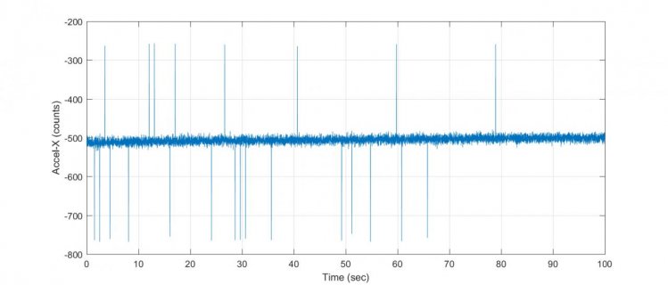
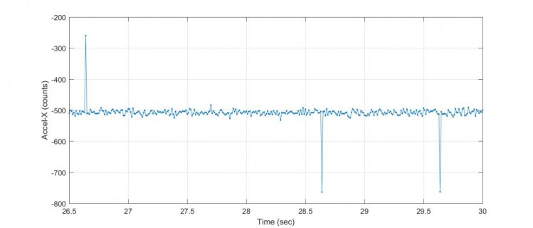
Occasionally, I still get dropouts with my LSM6DS3 IMU sensor with a CAT5 cable (unshielded, roughly 4 feet long) via I2C. I tried a CAT6 cable, shielded with a wire-mesh sleeve, but still occasional dropouts. The dropout is a sudden random spike roughly 255 counts (2^8) above the noise floor at a single time sample. See time history plots below. First figure is an overview plot followed by an up-close view.

dropouts.jpgdropouts_zoom.jpg

Then I placed the sensor directly on the breadboard with the Teensy 3.2, and still, dropouts. In all cases, I have 4.7K pull-ups on the SDA and SCLK lines. So it's not the cable. I've seen these dropouts on the Arduino Due also, which is the main reason why I purchased a Teensy board.

I believe I tracked down the issue. The LSM6DS3 sends accel & gyro readings as a 16-bit result in two's complement (two 8 bit records - first is the LSB followed by the MSB). I plotted the LSB and MSB and the merged 16-bit result. Left undisturbed, the MSB is steady while the LSB changes randomly with noise - this is normal. However, when a dropout happens, the usually steady MSB is off by a single bit. One bit of MSB is 2^8 or 255 counts - this is the magnitude of the dropouts.

At this point I don't think it's the Teensy or Arduino Due, it's likely the LSM6DS3 sensor from ST. Now that I know more, I'll try SPI again.
 
Last edited:
Okay, I tried SPI with the LSM6DS3 IMU using the Teensy 3.2 board. For the settings I tried, it works great. Not only does it run faster (roughly 20X), no dropouts as observed with I2C. SPI is rock solid. Here's complete example code for your information - it reads accel & gyro data at a sample rate of 100hz:

Code:
#include <SPI.h> 


//  TIMING
#define MAXSAMPLE 1000            // Number of data samples:
#define CLAW_FS   100             // Control System Sample Rate (long) (Hz)
volatile boolean  PING  = false;  
IntervalTimer     clawtimer;      // Timer Object for CLAW


void beacon()
{
    PING = true;      
}

boolean wow()
{
    return PING;
}


// SPI Pins
#define   READ    0x80  
#define   WRITE   0x00
#define   MOSIX   11
#define   MISOX   12
#define   SCKX    13
#define   SSX     10

SPISettings  SETA(10e6, MSBFIRST, SPI_MODE0); 


// IMU REGISTERS
uint8_t   address_accelx = 0X28;
uint8_t   address_accely = 0X2A;
uint8_t   address_accelz = 0X2C;
uint8_t   address_gyrox  = 0X22;  
uint8_t   address_gyroy  = 0X24;
uint8_t   address_gyroz  = 0X26;


// IMU COUNTS
int16_t   caccx, caccy, caccz, cgyrox, cgyroy, cgyroz;


// STREAM VARIABLES
#define MAXLINE 136
char  nmeac[MAXLINE];


void spi_initialize()
{
    pinMode(SSX, OUTPUT);
    digitalWrite(SSX,HIGH);
 
    SPI.setMOSI(MOSIX);
    SPI.setMISO(MISOX);
    SPI.setSCK(SCKX);
    SPI.begin(); 
}


uint8_t  spi_read( SPISettings SETX, uint8_t target)
{
    uint8_t  out1;
    uint8_t  out2;

    SPI.beginTransaction(SETX);
      
    digitalWrite(SSX,LOW);
    
    delayMicroseconds(1);
    out1 = SPI.transfer(target | READ);    
    out2 = SPI.transfer(0x00);  
            
    digitalWrite(SSX,HIGH); 

    SPI.endTransaction();

    return out2;
}


int16_t  spi_read_16bit( SPISettings SETX, uint8_t target)
{
    uint8_t   out1, out2, out3;
    int16_t  out4;

    SPI.beginTransaction(SETX);
     
    digitalWrite(SSX,LOW);
    
    delayMicroseconds(1);
    out1 = SPI.transfer(target | READ);    
    out2 = SPI.transfer(0x00);  
    SPI.endTransaction();


    SPI.beginTransaction(SETX);

    delayMicroseconds(1);
    out3 = SPI.transfer(0x00);  
            
    digitalWrite(SSX,HIGH); 

    SPI.endTransaction();


    out4 = (int16_t)(out2 | (out3 << 8));

    return out4;
}


void  spi_write( SPISettings SETX, uint8_t target, uint8_t data2write)
{
    SPI.beginTransaction(SETX);

    digitalWrite(SSX, LOW);   // Select chip 
           
    delayMicroseconds(1);
    SPI.transfer(target | WRITE);
    SPI.transfer(data2write);
                
    digitalWrite(SSX, HIGH);   // De-select chip

    SPI.endTransaction();
}


void init_imu()
{
    uint8_t address, target, writeout;
    uint8_t result;
         
    Serial.println("Who Am I: 101");
        target = 0x0F;  // WHO-AM-I BYTE   
        Serial.println(spi_read( SETA, target ));

    Serial.println("Continuous or not");
        target   = 0X12;
      //writeout = 0X00;   // DO NOT USE; PREVENTS TEENSY FROM READING 2ND BYTE OF ACCEL OR GYRO 16-BIT READING
        writeout = 0X04;   // 00000100
        spi_write( SETA, target, writeout);

    Serial.println("Decimation:");
        target   = 0X08;
        writeout = 0X09;   
        spi_write( SETA, target, writeout);
     
    Serial.println("Accel Settings:");
        target   = 0X10;
        writeout = 0X4E;  // 0100 1110,  odr: 104Hz, +/-8g, filter: 100hz
        spi_write( SETA, target, writeout);

    Serial.println("Gyro Settings:");
        target   = 0X11;
        writeout = 0X48;  // 0100 1000,  odr: 104hz, 1000 dps
        spi_write( SETA, target, writeout);

    Serial.println("CTRL4_C (13h) :");
        target   = 0X13;
        writeout = 0X80;  // bandwidth determined by setting BW_XL[1:0]
        spi_write( SETA, target, writeout);
}


void setup()
{
    double   microsec1;
    int  ii;


    // INITIALIZE 
    Serial.begin(115200); 

    Serial.println("Hello:");

    spi_initialize();

    init_imu();
     

    // TIMER STUFF
    microsec1 = 1.0e6/CLAW_FS; 
    clawtimer.begin( beacon, microsec1 );      

    delayMicroseconds(1000000);


    PING  = false;
    ii    = 0;       
    
    while (ii<MAXSAMPLE)
    {        
        // FORCE FIXED TIME STEP
        while ( wow()!=true);         
        PING  = false;
        
        // GET IMU Measurements.  Units: counts
        //------------------------------------------
        caccx  = spi_read_16bit( SETA, address_accelx);
        caccy  = spi_read_16bit( SETA, address_accely);
        caccz  = spi_read_16bit( SETA, address_accelz);
        cgyrox = spi_read_16bit( SETA, address_gyrox );
        cgyroy = spi_read_16bit( SETA, address_gyroy );
        cgyroz = spi_read_16bit( SETA, address_gyroz );


        sprintf(nmeac, "  %d %d %d %d %d %d \r\n",  caccx, caccy, caccz, cgyrox, cgyroy, cgyroz );

        Serial.print(nmeac);
                
        ii++;        
    }  
    
    clawtimer.end();       
}


void loop()
{ 
}

Thanks for you help.
 
Status
Not open for further replies.
Back
Top