Teensy listen to audio shield without controlling it

Status
Not open for further replies.

josechow

Well-known member
Hey,

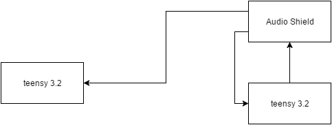
So I was wondering if it is easy to setup an external teensy 3.2 to listen to the audio shield's digital audio data while the audio shield is being controlled by another teensy 3.2. Illustration below. The external teensy 3.2 on the left just needs to listen to the audio data captured by the shield and reproduces the analog signal. I want to do this because the audio shield is taking in a piezo signal. The digital signal to the external teensy is separated by a 25 foot cable.
Untitled Diagram3.png

I think it will work (program the left teensy to accept a i2s input from a parallel tx line coming out of the shield), but I wanted to verify it can be done before I bought the parts :)

Thanks in advance.
 
There might be a catch: The external Teensy has to work in I2S slave mode, and that will propably mess up the timing of incoming data (I2S stream) in respect to outgoing data (DAC or PWM).
Info from the Audio Design Tool:
Slave mode I2S should not used in the same project as ADC, DAC and PWM signals. Differences in timing between the I2S device and Teensy's clock can cause occasional audio glitches when I2S slave mode is used together with other input or output objects based on Teensy's timing.

Only one I2S input and one I2S output object may be used. Master and slave modes may not be mixed (both must be of the same type).

This could be solved by using an Asynchronous Sample Rate Converter (ASRC), but that would be quite an advanced level project IMHO.
-Ben
 
Even if this could work (unlikely without better I2S slave mode support), I2S isn't meant to drive a long 25 foot cable!

I2S is really only meant to connect between 2 chips on the same circuit board.
 
Even if this could work (unlikely without better I2S slave mode support), I2S isn't meant to drive a long 25 foot cable!

I2S is really only meant to connect between 2 chips on the same circuit board.

Yeah... for what ever reason I thought it was the same as I2C. I forgot what speeds are involved here. The work around I suppose would be an FFT on the incoming data and send the bin values over I2C and IFFT it on the other side? but I lose fidelity :(

A 1024 bit fft should be good enough right? I think I might start running into CPU processing problems because I have a bunch of other operations I need to run on the teensy connected to the audio shield.
 
What does the 25-foot away teensy do with the data ?

DAC it out to an amplifier. I would run the analog signal the entire way instead of digital, but in parallel with the audio line is power and i2c lines for other communication needs; So I get a dirty signal to say the least. I've tried to push the frequency offenders out of hearing range (which is what I want) and band pass it, but that hasn't worked as well as I wanted it to.
 
In that case, I'd use I2S to TOSLink converters and link the Teensys through a glass fiber cable.

You don't need a converter - the teensy can output SPDIF - there's an existing output-object. Or add a simple TOSLINK-adapter... (no electronics, just the socket... (hehe..it works with a simple, bright LED, too.. but that's not "professional" :) )

edit: oh..ok..you can't use an audioboard the same time..
 
Last edited:
Converting to and from S/PDIF might solve the problem of crosstalk, but you'd still have a data stream that's asynchronous to the DAC. I suggest going back to analog audio, but with a shielded cable and balanced (differential) signaling. Use a strong balanced line driver like TI's DRV134/135 and a good differential line receiver like INA134 or maybe THAT1200. If you have the supply voltages available I'd definitely go that route, as it has been proven successful in countless audio studios around the world. Differential signaling (or balanced as it is called in the audio world) can make a huge difference, it's absolutely not limited to high speed signals like LVDS interfaces.
-Ben
 
The DAC get's its clock from the SPDIF-Signal, it's encoded there.

Edit: And for the transmitting Teensy, there is no converter needed.. it can output that signal directly.
 
Last edited:
Converting to and from S/PDIF might solve the problem of crosstalk, but you'd still have a data stream that's asynchronous to the DAC. I suggest going back to analog audio, but with a shielded cable and balanced (differential) signaling. Use a strong balanced line driver like TI's DRV134/135 and a good differential line receiver like INA134 or maybe THAT1200. If you have the supply voltages available I'd definitely go that route, as it has been proven successful in countless audio studios around the world. Differential signaling (or balanced as it is called in the audio world) can make a huge difference, it's absolutely not limited to high speed signals like LVDS interfaces.
-Ben

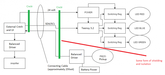
Like this Ben?

Untitled Diagram666.png

I should have uploaded this before. I need the interconnecting cable to minimize the number of chords between the two controllers.
 
The DAC get's its clock from the SPDIF-Signal, it's encoded there.

Edit: And for the transmitting Teensy, there is no converter needed.. it can output that signal directly.

Is there a SPDIF Input Object in the audio library? The GUI design tool only shows an output object.

If that's the case I'd also strongly lean towards the SPDIF-Solution instead of analog balanced.
 
Is there a SPDIF Input Object in the audio library? The GUI design tool only shows an output object.

If that's the case I'd also strongly lean towards the SPDIF-Solution instead of analog balanced.

Nope, and i didn't mention input.
 
Nope, and i didn't mention input.

Oh ok. I thought this would be a way to drive the DAC with the recovered clock from the SPDIF signal.
Or am I missing something? My current understanding is that SPDIF will solve the data integrity problem one would have with straight I2S over long wires, but I don't see a solution to the asyncronous DAC clocking problem. Please correct me if I'm wrong.

From the drawing and given that the Teensy doesn't do anything with the data, this looks really like two completely unrelated systems? One system with the remote T3, talking via I2C to the T3 that does something to the LED regulators. And the other system consisting of the pickup, line and amplifier. In this case you could just go from the piezo pickup to a DI-Box (https://en.wikipedia.org/wiki/DI_unit) and from there to the amp. I don't know if DIs can handle piezo pickups though.

-Ben
 
Status
Not open for further replies.
Back
Top