K66 Beta Test

Status
Not open for further replies.
I am now back to my computer, so I have made a version of Cores and SPI projects without my psuedo pins for using the SDCard.

I then tested using my SPIN library and updated ILI9341_t3 (t3n) library and was able to run the ILI9341t3 displays with only one unique SPI CS pin on each on SPI1 and SPI2.

To test SPI2, I soldered in Header pins into the 2x5 header on the board just below SDCard pins. From my previous posting about pin numbers with Pauls updated pin definitions, these pins are:
Code:
3.3V  [] ()  GND
   48  () ()  47
   57  () ()  56
   51  () ()  52
   53  () ()  55
So testing using my updates we have:
Code:
#ifdef SPI2_DISP
#define TFT_DC 55 // 0xe4
#define TFT_CS 57 // 0xe5
#define TFT_SCK 53 //0xe2
#define TFT_MISO 51 // 0xe3
#define TFT_MOSI 52 // 0xe1
#define TFT_RESET 56
ILI9341_t3n tft = ILI9341_t3n(TFT_CS, TFT_DC, TFT_RESET, TFT_MOSI, TFT_SCK, TFT_MISO, &SPIN2);
#endif

I also tested for SPI1 using the pins:
Code:
#ifdef SPI1_DISP
#define TFT_DC 6 // 0xe4
#define TFT_CS 7 // 0xe5
#define TFT_SCK 32 //0xe2
#define TFT_MISO 1 // 0xe3
#define TFT_MOSI 0 // 0xe1
#define TFT_RESET 8
ILI9341_t3n tft = ILI9341_t3n(TFT_CS, TFT_DC, TFT_RESET, TFT_MOSI, TFT_SCK, TFT_MISO, &SPIN1);
#endif

So did Pull requests on SPI project as well as CORES.

Kurt
 
Last edited:
Updated Wire.cpp - To include the ability to use the new pins for SCL and SDA.

Tested using SRF08 program...
Code:
  Wire.setSDA(48);
  Wire.setSCL(47);
  Wire.begin();

I pushed the changes up to github and did a pull request.

Note: I have not updated the i2c_t3 library for these pins. Also I have not updated i2c_t3, as we should now be able to create Wire3 on pins SDA(56), SCL(57) both ALT pins 2... Again as shown on previous post, these pins are available on the 2x5 connector on the test boards.

Next up look at creating Serial6
 
KurtE - Looks like I may have to solder to my K66 after all to get those pins. When I get Ethernet I can move my Wire2 to Wire3. And I can merge in my Serial port looping and add Serial6.
If you have or make and definitive posts on your many GITHUB contributions I could get them linked.

Can you confirm that the 'SPI PullUps on CS and D/C?' are needed for proper function - especially when I try to use the shared display Touch?

<edit>: P-ups on CS and T_CS pins - just used a meter.
 
Last edited:
I don't believe you need Pullups on CS or DC lines, as they are are simply signals to the display that it should pay attention to stuff coming on the SPI pins or not and likewise if it is listening, should it interpret the byte as a command or as data...

However, if you have multiple SPI devices connected up to the same SPI buss, then you do need to make sure that only one CS is asserted at a time. If all of your devices have been setup, hopefully each library will initialize it's CS pin to the right state. However if you don't actually initialize that device, then it's CS pin may be floating and potentially be set LOW, which is the asserted state. This is what happened on my setup when I was testing different displays (one at a time) and had two of them on SPI1. Pin 10 was LOW and caused it to interpret all of the commands I was sending to the other display as well.

Hope that make sense.

As for Serial6, should be fun. The code is not a straight copy of Serial1-5 which use the UART system, but instead will use the LPUART system, which has different registers and probably capabilities. Hopefully I should be able to get it working.
 
Teensy Loader 1.29-beta3:

touchRead() works as expected along with basic Serial.print() and friends.

fastled isn't working for a 180 LED strip of APA102s, but what I tried was a quick smoke test. A Teensy 3.0 was able to drive the strip with pins 2 and 3 for data and clock respectively.

Same code on the K66 made some light appear and wasn't obviously hung, but not many lights, not the patterns I was expecting and the LEDs would sometimes turn off after a second or so. The power supply is rated for 10A at 5V. The wiring was simplistic: connected at one end, no added components.

Trying to figure out most efficient way to get from here to a valid test. I've got parts on hand including a PJRC Prop Shield LC, discrete SMT AND gates, a DIP level shifter similar to the one Paul recommends, voltage regulators, resistors, capacitors, etc. One thing I don't have is an oscilloscope, so signal integrity leaves me guessing.

Not sure how to prioritize among the following:

  1. power/ground at both ends of the strip
  2. clock/data terminated with a voltage divider
  3. clock/data level shifter
  4. measure the voltage drop across the strip
  5. add capacitor between power and ground
  6. add resistors on the signal lines close to the K66
  7. experiment with something completely different because without an oscilloscope, this isn't efficient.

Very quick and very dirty code below working nicely with a T3.2 and a 1m strip of 96 APA102s. This application also omits level shifters, but does have voltage dividers at the far end, though the thing that made the most difference was an adequate power supply.

Code:
#include "FastLED.h"

#define LED_TYPE APA102
#define COLOR_ORDER BGR


const int DATA_PIN = 2;
const int CLOCK_PIN = 3;
int BRIGHTNESS = 8;
const unsigned int NUM_LEDS = 96;
CRGB leds[NUM_LEDS];


void setup() {
  Serial.begin(57600);
  Serial1.begin(57600);
  delay(500);
  //  FastLED.addLeds<LED_TYPE, DATA_PIN, CLOCK_PIN>(leds, NUM_LEDS).setCorrection(TypicalLEDStrip);
  // My strip seems to have a purple cast, at least at low brightness.
  FastLED.addLeds<LED_TYPE, DATA_PIN, CLOCK_PIN, COLOR_ORDER, DATA_RATE_MHZ(12)>(leds, NUM_LEDS);
  FastLED.setCorrection(0xFFFFCC);
  //  FastLED.setMaxPowerInMilliWatts(2500);
  // Use hardware SPI.
  //FastLED.addLeds<APA102,11,13,RGB,DATA_RATE_MHZ(10) >(leds,NUM_LEDS);
  fill_rainbow(leds, NUM_LEDS, 0, 240);
  FastLED.setBrightness(BRIGHTNESS);
  FastLED.setDither(DISABLE_DITHER);
  //  FastLED.setMaxRefreshRate(1000);
  // Supported in 3.1.1.
  // limit my draw to 1A at 5v of power draw
  //FastLED.setMaxPowerInVoltsAndMilliamps(5,500);
}


char old_mode = '*';
char mode = 'f';
uint8_t phase = 0;


int mode_index = 0;
int brightness_index = 1;


int read_state = 0;
char mode_candidate = 0;
void loop() {
  // "3: Boot system code via Flash (default)"
  // Serial1.println("3");
  // "Press the [1], [2], [3] or [4] key and hit [enter] to select the debug level"
  // "Please press Enter to activate this console."
  // "|__| W I R E L E S S   F R E E D O M"
  // "root@a51:/# "
  const char* prefix = "^teensy:";
  const char* suffix = "$%";
  if (Serial1.available()) {
    char byte(Serial1.read());
    Serial.write(byte);
    if (read_state < 8) {
      if (byte == prefix[read_state]) {
        Serial.print("~");
        Serial.print(byte);
        ++read_state;
      } else {
        read_state = 0;
      }
    } else if (read_state == 8) {
      mode_candidate = byte;
      Serial.print("Candidate: `");
      Serial.print(byte);
      Serial.println("`.");
      ++read_state;
    } else if (read_state < 11) {
      if (byte == suffix[read_state - 9]) {
        Serial.print("*");
        ++read_state;
      } else {
        Serial.print("ñ");
        read_state = 0;
      }
    } else if (read_state == 11) {
      read_state = 0;
      mode = mode_candidate;
      Serial.print("Setting mode to '");
      Serial.print(mode);
      Serial.println("'.");
    } else {
      Serial.print("read_state: ");
      Serial.print(read_state);
      Serial.println(".");
      read_state = 0;
    }
  }
  while (Serial.available()) {
    unsigned int r = Serial.read();
    switch (r) {
      case 'a':
      case 'b':
      case 'c':
      case 'd':
      case 'e':
      case 'f':
      case 'g':
      case 'l':
      case 'm':
      case 'o':
      case 'r':
      case 'u':
      case 'w':
      case 'y':
      case 'z':
      case '0':
      case '1':
      case '2':
      case '3':
      case '4':
      case '5':
      case '6':
      case '7':
      case '8':
      case '9':
        old_mode = mode;
        mode = r;
        Serial.println(mode);
    }
  }
  int t15 = touchRead(15);
  if (t15 > 600) {
    Serial.println("Off");
    mode = '0';
    delay(500);
  }


  int t16 = touchRead(16);
  if (t16 > 620) {
    Serial.println("Next");
    ++mode_index;
    if (11 < mode_index) mode_index = 0;
    mode = "abcfgmoruwyz"[mode_index];
    delay(500);
  }


  int t17 = touchRead(17);
  if (t17 > 819) {
    Serial.println("Dimmer");
    if (brightness_index) {
      mode = "0123456789"[--brightness_index];
    }
    delay(500);
  }


  int t18 = touchRead(18);
  if (t18 > 582 + 100) {
    Serial.println("Brighter");
    if (brightness_index < 4) {
      mode = "0123456789"[++brightness_index];
    }
    delay(500);
  }


  int t19 = touchRead(19);
  if (t19 > 580 + 100) {
    Serial.println("On");
    mode = '1';
    delay(500);
  }


  int t22 = touchRead(22);
  if (t22 > 723) {
    Serial.println("Previous");
    if (mode_index) {
      mode = "abcfgmoruwyz"[--mode_index];
    } else {
      mode_index = 11;
      mode = "abcfgmoruwyz"[mode_index];
    }
    delay(500);
  }


  if (mode != old_mode) {
    if (mode == 'a') {
      fill_solid(leds, NUM_LEDS, CRGB::Blue);
      for (unsigned int i = 0; i < NUM_LEDS; i += 2) {
        leds[i] = CRGB::White;
      }
      Serial1.println("ls --color=never");
    } else if (mode == 'd') {
      fill_solid(leds, NUM_LEDS, CRGB::Red);
      for (unsigned int i = 0; i < NUM_LEDS; i += 3) {
        leds[i] = CRGB::White;
      }
    } else if (mode == 'e') {
      fill_solid(leds, NUM_LEDS, CRGB::Orange);
      for (unsigned int i = 0; i < NUM_LEDS; i += 4) {
        leds[i] = CRGB::White;
      }
    } else if (mode == 'f') {
      fill_solid(leds, NUM_LEDS, CRGB::Yellow);
      for (unsigned int i = 0; i < NUM_LEDS; i += 5) {
        leds[i] = CRGB::White;
      }
    } else if (mode == 'z') {
      fill_rainbow(leds, NUM_LEDS, phase, 256 / NUM_LEDS);
    } else if (mode == 'r') {
      Serial.println("red\n");
      fill_solid(leds, NUM_LEDS, CRGB::Red);
    } else if (mode == 'g') {
      Serial.println("green\n");
      fill_solid(leds, NUM_LEDS, CRGB::Green);
    } else if (mode == 'l') {
      Serial.println("low\n");
      fill_solid(leds, NUM_LEDS, CRGB::Black);
      FastLED.setBrightness(8);
      leds[0] = CRGB::White;
    } else if (mode == 'b') {
      Serial.println("blue\n");
      fill_solid(leds, NUM_LEDS, CRGB::Blue);
    } else if (mode == 'c') {
      Serial.println("cyan\n");
      fill_solid(leds, NUM_LEDS, CRGB::Cyan);
    } else if (mode == 'y') {
      Serial.println("yellow\n");
      fill_solid(leds, NUM_LEDS, CRGB::Yellow);
    } else if (mode == 'o') {
      Serial.println("orange\n");
      fill_solid(leds, NUM_LEDS, CRGB::OrangeRed);
    } else if (mode == 'm') {
      Serial.println("magenta\n");
      fill_solid(leds, NUM_LEDS, CRGB::Magenta);
    } else if (mode == 'u') {
      Serial.println("red and blue\n");
      fill_solid(leds + 0, 32, CRGB::Blue);
      fill_solid(leds + 32, 32, CRGB::Red);
      fill_solid(leds + 64, 32, CRGB::Blue);
    } else if (mode == 'w') {
      Serial.println("white\n");
      fill_solid(leds, NUM_LEDS, CRGB::White);
    } else if ('0' <= mode && mode <= '9') {
      int intensity = 0;
      switch (mode) {
        case '1': intensity = 8; break;
        case '2': intensity = 15; break;
        case '3': intensity = 23; break;
        case '4': intensity = 31; break; // maximum brightness
        case '5': intensity = 47; break;
        case '6': intensity = 63; break;
        case '7': intensity = 127; break;
        case '8': intensity = 190; break;
        case '9': intensity = 255; break;
        default: intensity = 0;
      }
      if (intensity > 31) {
        Serial.println("Too bright!");
        intensity = 31;
      }
      Serial.println(intensity);
      FastLED.setBrightness(intensity);
    }
    old_mode = mode;
    FastLED.show();
  }
  if (mode == 'z') {
    fill_rainbow(leds, NUM_LEDS, phase, 256 / NUM_LEDS);
    FastLED.show();
    FastLED.delay(10);
  }
  phase += 2;
}

OT: Sorry I haven't been more active. Got laid off just after I got the beta board. Advice or leads for software development near San Jose, CA welcome. PM me.
 
I don't believe you need Pullups on CS or DC lines, as they are are simply signals to the display that it should pay attention to stuff coming on the SPI pins or not and likewise if it is listening, should it interpret the byte as a command or as data...

However, if you have multiple SPI devices connected up to the same SPI buss, then you do need to make sure that only one CS is asserted at a time. If all of your devices have been setup, hopefully each library will initialize it's CS pin to the right state. However if you don't actually initialize that device, then it's CS pin may be floating and potentially be set LOW, which is the asserted state. This is what happened on my setup when I was testing different displays (one at a time) and had two of them on SPI1. Pin 10 was LOW and caused it to interpret all of the commands I was sending to the other display as well.
...

That will help - I'll try to stabilize my setup with that in mind. Using the 2.4" 9341 the second touch SPI is not connected. Often runs fine but something is odd with touch version, just wasn't sure about pullups being needed.
I got female cabled units I put pins on the end - wires are 5" - then into sockets to sockets across proto board - I wonder if length is getting me?
 
Serial6? - T3.4 and T3.5 will be different (I Think).

That is with Current Beta board
Code:
47	D8	DISABLED		PTD8	I2C0_SCL			LPUART0_RX	FB_A16
48	D9	DISABLED		PTD9	I2C0_SDA			LPUART0_TX	FB_A17
But if you look at the processor sheet for the T3.4, you see on these pin:
Code:
137 C9 A10 — PTD8 DISABLED PTD8 I2C0_SCL UART5_RX FB_A16
138 B9 A9 — PTD9 DISABLED PTD9 I2C0_SDA UART5_TX FB_A17
Pardon the formatting, but what is interesting is that on this board there is an UART5 and there is not an LPUART0

I noticed there were differences already in kinetis.h for these two boards. T3.4 has the define: #define HAS_KINETISK_UART5
and the one we are using: #define HAS_KINETISK_LPUART0

My question is, should I create a Serial6 for this board or should we only do so for the T3.4?
 
Note: I have not updated the i2c_t3 library for these pins. Also I have not updated i2c_t3, as we should now be able to create Wire3 on pins SDA(56), SCL(57) both ALT pins 2... Again as shown on previous post, these pins are available on the 2x5 connector on the test boards.

I've updated the i2c_t3 library given the recent pin information. It is attached below. As far as i2c_t3 lib on GitHub, I'm cleaning the examples now, and then the docs, and then I'll push all the updates and update the i2c_t3 thread.

EDIT: library has been updated on GitHub, refer to this post:
https://forum.pjrc.com/threads/34808-K66-Beta-Test?p=110994&viewfull=1#post110994
 
Last edited:
Looking forward to this new K66 board. What is the latest on the name (with the understanding that it is not final and subject to change)? Given all features and the outer edge pins, a name starting with "Teensy" is almost a misnomer. But I suppose you are stuck with that from a branding perspective.
 
I've updated the i2c_t3 library given the recent pin information. It is attached below. As far as i2c_t3 lib on GitHub, I'm cleaning the examples now, and then the docs, and then I'll push all the updates and update the i2c_t3 thread.
Good news on the i2c_t3 catching up! I linked p#8 to your post #808. Anything BETA specific could go in that sticky wiki linked post #808 perhaps - it's evolved a lot in this thread.


I don't believe you need Pullups on CS ... However, ... Hope that make sense.
Made sense - got me to the answer - I used a meter - the pullups on Paul's purple OSH video w/touch board: on CS and T_CS. I didn't have T_CS under software control so it was floating and stealing/corrupting SPI data it seems. Finished wiring that up - the touch has no provisions for SPI beyond CS and the IRQ pin I added. It does work on SPI0 when set up for the display though with just SPI.begin()?

So on alternate pins the Touch ILI9341 also works - I think I used standard T_3.2 pins when I got K66. Testing with my ColorButtonsMark3 code with just these changes:
Code:
ILI9341_t3 tft = ILI9341_t3(10, [B]20[/B], 255, 11, [B]14[/B], 12);
// ILI9341_t3::ILI9341_t3(cs, dc, rst, mosi, sclk, miso)
XPT2046_Touchscreen ts([B]21[/B], [B]15[/B]);  // CS is Param 1 and Param 2 - Touch IRQ Pin - interrupt enabled polling

@randomvibe - see post #8 - the current working name is Teensy 3.5

I made 'local' edits to ILI9341 "graphicstest" and those visible draw errors on rotation 1&3 go away. In testFilledRects() and testFilledRoundRects() needed: "min(tft9341.width(), tft9341.height())-1". That value is used as absolute number, not like the others that use "for( ...; i<min(...); ...)", so it overdraws by 1 and that causes it to do what I saw. In rotation 0&2 the error gets eaten but costs over 5ms each in perf test [k66@240MHz] - and it runs FINE and FASTER as F_BUS 120 (touch and no touch)::
Code:
// Rectangles (filled)      461294
// Rectangles (filled)      467094 << no -1
// Rectangles (filled)      434488 >> With -1 and 240 MHz K66 using F_BUS 120 Mhz
  n = min(tft.width(), tft.height());
  n = min(tft.width(), tft.height[B]())-1[/B];
// Rounded rects (filled)   503372
// Rounded rects (filled)   509048 << no -1
// Rounded rects (filled)   473963 >> With -1 and 240 MHz K66 using F_BUS 120 Mhz
  for(i=min(tft.width(), tft.height()); i>20; i-=6) {
  for(i=min(tft.width(), tft.height[B]())-1[/B]; i>20; i-=6) {
I also made the 5 changes to ili9341.[c&h] to Adafruit_GFX_Button_t3 from Adafruit_GFX_Button so it will link with Adafruit_SSD1306 using that name.
It looked so simple - I did a PaulStoffregen/ILI9341_t3/pull/28 and there are conflicts with other pending changes.

KurtE: Github finally worked for me first time! Changed my editor for UNIX_EOL and diffs were clean - except noted merge conflicts
> my pluggable 5" wire set plus self crimped pin to header to board to header on K66 is good now
> Added pin21 output set to 1 and I don't have to move that Touch CS pin to 3.3V when wired but not used!
> Now I have to unmount my K66 to put headers on those 'bottom' pins you put to use

Paul: 48 pins is overkill :) - I have 4 different displays running and I'm only using 17 data pins (plus 4 on GND & 8 on 3.3V). Of course 12 are needed for Ethernet
 
Last edited:
defragster: nice summary!

CS on ILI9341 display, I have a shield from Adafruit that has this, but I am not sure where it is... May look for it some more.

nox771 (and others): Thanks for the update! Wondering how best to handle T3.4. right now as we have no beta boards. Currently programs that include i2c_t3 will not compile if you set the board type to 3.4. I believe this is mainly since i2c_pins is not defined...

I think I need to take a pass in my spreadsheet and maybe make a new page with the 3.4 stuff, to see how many differences there are. As I mentioned yesterday there is a difference in UARTS, in T3.4 will has I believe UART5 whereas 3.5 has LPUART0...

Github: I am no expert at this. I do a lot of google to find out stuff. Example line endings and differences between windows an Linux. One option is shown: https://help.github.com/articles/dealing-with-line-endings/

Paul: 48 pins is overkill :) - I have 4 different displays running and I'm only using 17 data pins (plus 4 on GND & 8 on 3.3V). Of course 12 are needed for Ethernet
Sometimes you can never have too many pins. Note: I personally think we should expose real pin names for the SDCard pins (not my 0xe0-e5), but maybe 48-53. Yes would need simple adapter, which you could probably sell for a few bucks. But for those who don't need SD cards in their sketch it gives them 6 extra pins (plus +5v and Gnd) and these pins include full SPI1 set of pins including 3 CS pins.

Now back to figuring out LPUART. Right now trying to understand the clock source options. You can choose from MCGIRCLK, OSCERCLK, or shared with some other devices choice between (MCGFLLCLK, IR48CLK, USB1PFDCLK, MCGPLLCLK), now I believe that the choice in the later setup which is set in SIM_SOPT2[PLLFLLSEL] is already setup for other devices in the init code depending on clock speed... Lots to learn!

Kurt
 
nox771 (and others): Thanks for the update! Wondering how best to handle T3.4. right now as we have no beta boards. Currently programs that include i2c_t3 will not compile if you set the board type to 3.4. I believe this is mainly since i2c_pins is not defined...

That is correct, it won't compile for T3.4 due to lack of pin definitions. Once a new thread starts on T3.4 and has the pin information (as was originally in post #3), then I'll update it. Or does that info exist somewhere else already?
 
That is correct, it won't compile for T3.4 due to lack of pin definitions. Once a new thread starts on T3.4 and has the pin information (as was originally in post #3), then I'll update it. Or does that info exist somewhere else already?
It is my believe that the pin table is common to both boards, however what is actually on each of the pins (ALTn) may be different, as I saw with the UART5 vs LPUART0.

Example of those two (new) pins on T3.5, I have:
Code:
47  D8          PTD8    I2C0_SCL                        LPUART0_RX  FB_A16  
48  D9          PTD9    I2C0_SDA                        LPUART0_TX  FB_A17
On the T3.4 the D8 and D9 pins look more like:
Code:
47  D8          PTD8     I2C0_SCL UART5_RX                            FB_A16
48  D9          PTD9     I2C0_SDA UART5_TX                            FB_A17
Again the formatting here may be off, and I know now I need to make a pass through and create new page in spreadsheet
The differences on these two pins is UART5(ALT3) and LPUART0(ALT5)
 
From the manuals:
K64:
"In this chip, the 100-pin package has 5 UARTs. The 121-pin and 144-pin packages have
6 UART modules."

K66:
This chip contains five UART modules. This section describes how each module is
configured on this device.
PLUS:
1 x low-power uart

So the difference is, that the 6th uart is low-power on the K66 - so they must be handled differently.

The question is, which package of K64 will be used.
 
Last edited:
Please do not do this. If the problem doesn't magically resolve itself when you use other computers, please send the whole thing back to us. I'd like to work with it here, while it's still in this mysterious state.

@Paul,
Due to custom issues, I was not able to send the K66 back yet (they always asked new documents), so I connected the K66 again to my laptop

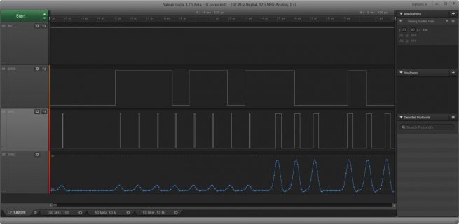
Please have a look on the screenshot of my saleae LA of the RST,SWD,SWC pins
SWC_200716_screenshot.jpg
The picture is made after prog button pressed
The SWC pin is both digital and analog. (50 MHz digital 12.5 MHz analog)
It seems that SWC line exceeds some voltage (peak is 0.349V), which at least the LA recognizes as high. Could this also be with the K66, that is the K66 recognizes a high where none should be?
If this were the case, what could I do to clean up the signal? Would it help?
Or is this intended behavior?
 
Last edited:
Paul,
Have the board names, board defines, and MCU defines been finalized?
I saw in post #48 that you were still undecided.
Have you finalized on:
"Teensy 3.4", TEENSY34, __MK64FX512__
"Teensy 3.5", TEENSY35, __MK66FX1M0__

I need to know these to complete the openGLCD code updates and documentation.
 
Did quick scan through the IO pins as the map to what I think T3.4 will be.

The main differences I see are the UART5/LPUART0 and it looks like E10/E11 on T3.4 are NOT SPI pins...
 
Cool that the K64/K66 chip pin and functions are similar - of course Paul knew that when he decided on the 3.3V and 5V capable formats of the two. Hopefully the CPU/BUS speeds are similarly adaptable.

I'd still vote for the alliterative value of 3.6==K66: "Teensy 3.6", TEENSY36, __MK66FX1M0__

My quad display (with other) ran fine over night - an currently. Temp at 99°F on my OC'd K66. Just started monitoring my loop() time - getting 1.3-6.5 FPS - mostly limited by ILI9341 benchmark.

Very cool that an 'unused' SD card can make a high speed connector with an adapter to "6 extra pins (plus +5v and Gnd) and these pins include full SPI1 set of pins including 3 CS pins". Hopefully a simple adapter will get published. Ick - 5V - seems like it will need a 3.3 LDO version, and maybe a debug blinky onehorse version.

New Notes from Kurt on P#8. I'm looking for sample sketch to use the SD card I haven't touched yet. I got a fresh 64GB flash I was thinking I might log some random numbers on to see how random they are for my next random^2 test.

Mail Came! - Looks like I'll be adding 100Mb Ethernet to my test sketch - even with pins the adapter is only as big as my finger - my '486' PC in 1991 had a stuffed double wide full length ethernet adapter that was only 10Mb. Now if I could just find the post for hookup notes and code . . . oh yeah - POST #8!
 
Last edited:
I'd still vote for the alliterative value of 3.6==K66: "Teensy 3.6", TEENSY36, __MK66FX1M0__

Assuming the board is not perfect and a modified version is released, and PJRC avoids symbols such as "+" or "++", the alliteration falls apart. Too bad PRJC can't use ATOM 3.6. Atom, as in small be powerful.

What will the retail price be, roughly?
 
Assuming the board is not perfect and a modified version is released, and PJRC avoids symbols such as "+" or "++", the alliteration falls apart. Too bad PRJC can't use ATOM 3.6. Atom, as in small be powerful.
What will the retail price be, roughly?

Not a safe assumption - this is the Beta thread and first public view of a well planned and refined upgrade. Seems like this would be good as it is after a month with it. And the '6' would still be there in ".6?" in any case. But I don't expect it will change.
Paul mentioned a goal price on an old thread once - hopefully BOM allow for that - will wait for PJRC to say - it'll be a bargain though
 
Ethernet board plugged in - unmodified K66 - two green lights with activity. On the network and picking up network traffic, won't respond to PING.

At 240 MHz I get ID3 mismatch with sketch PJRC k66_ethernet:
Ethernet Testing
----------------
enetbufferdesc_t size = 32
rx_ring size = 384
MDIO PHY ID2 (LAN8720A should be 0007): 7
MDIO PHY ID3 (LAN8720A should be C0F?): 40F8

My phone with 'FING' shows PJRC.COM with MAC 04:E9:E5:00:00:01, but like my PC a PING is 100% packet loss?
My output below doesn't have line below in Manitou Configuration summary do I have the right sketch?
"PHY control reg 0x3100 100mbs, auto negotiate, full duplex"

ID3 looks better at 120 MHz with a match on PJRC and the Manitou sketch output here:
Code:
Ethernet Testing
----------------

120000000
192.168.1.120
enetbufferdesc_t size = 32
rx_ring size = 384
buffer size 1520
RX buffers 12
TX buffers 10
MDIO PHY ID2 (LAN8720A should be 0007): 7
MDIO PHY ID3 (LAN8720A should be C0F?): C0F1
PHY BCR control reg 0x3100
PHY status reg 0x782D
PHY reg 17 0x2
MPU_RGDAAC0 0x37DF7DF
SIM_SCGC2 0x1
SIM_SOPT2 0x3D10C0
ENET_PALR 0x4E9E500
ENET_PAUR 0x18808
ENET_EIR 0x0
ENET_EIMR 0xA000000
ENET_ECR 0xF0000112
ENET_MSCR 0x1E
ENET_MRBR 0x5F0
ENET_RCR 0x45F2D104
ENET_TCR 0x104
ENET_TACC 0x1
ENET_RACC 0x80
ENET_MMFR 0x60460002
ARP request: 192.168.1.77

data in, len=62
flags 0x800
ARP response: 192.168.1.77 (E8:9D:87:6E:EE:2A) 240 us

data in, len=94
flags 0x880
IPv4 Packet, src=192.168.1.77, dst=192.168.1.255, type=17

data in, len=94
flags 0x880
IPv4 Packet, src=192.168.1.77, dst=192.168.1.255, type=17

data in, len=94
flags 0x880
IPv4 Packet, src=192.168.1.77, dst=192.168.1.255, type=17

data in, len=94
flags 0x880
IPv4 Packet, src=192.168.1.77, dst=192.168.1.255, type=17

data in, len=94
flags 0x880
IPv4 Packet, src=192.168.1.77, dst=192.168.1.255, type=17

data in, len=76
flags 0x800
IPv4 Packet, src=192.168.1.77, dst=192.168.1.120, type=1
  Protocol is ICMP:
  echo request:
   id = 1
   sequence number = 45

data in, len=62
flags 0x880
ARP  Who is 192.168.1.109 from 192.168.1.80 (00:0A:CD:19:94:07)

data in, len=94
flags 0x880
IPv4 Packet, src=192.168.1.77, dst=192.168.1.255, type=17

data in, len=94
flags 0x880
IPv4 Packet, src=192.168.1.77, dst=192.168.1.255, type=17

data in, len=94
flags 0x880
IPv4 Packet, src=192.168.1.77, dst=192.168.1.255, type=17

data in, len=62
flags 0x2880
ARP  Who is 192.168.1.109 from 192.168.1.80 (00:0A:CD:19:94:07)

data in, len=94
flags 0x880
IPv4 Packet, src=192.168.1.77, dst=192.168.1.255, type=17

data in, len=94
flags 0x880
IPv4 Packet, src=192.168.1.77, dst=192.168.1.255, type=17

data in, len=94
flags 0x880
IPv4 Packet, src=192.168.1.77, dst=192.168.1.255, type=17

data in, len=94
flags 0x880
IPv4 Packet, src=192.168.1.77, dst=192.168.1.255, type=17

data in, len=94
flags 0x880
IPv4 Packet, src=192.168.1.77, dst=192.168.1.255, type=17

data in, len=62
flags 0x880
ARP  Who is 192.168.1.109 from 192.168.1.80 (00:0A:CD:19:94:07)
in 18 out 2 arp 4 ip 14  tcp 0 udp 0 ulth 0 icmp 1 bcast 16 mcast 0
rxcnt 18 txcnt 2

data in, len=190
flags 0x880
IPv4 Packet, src=192.168.1.82, dst=192.168.1.255, type=17

data in, len=62
flags 0x880
ARP  Who is 192.168.1.1 from 192.168.1.82 (64:BC:0C:65:3A:21)

data in, len=62
flags 0x800
ARP  Who is 192.168.1.120 from 192.168.1.77 (E8:9D:87:6E:EE:2A)
ARP Reply:
 E8 9D 87 6E EE 2A 00 00 00 00 00 00 08 06 00 01
 08 00 06 04 00 02 04 E9 E5 00 00 01 C0 A8 01 78
 E8 9D 87 6E EE 2A C0 A8 01 4D

data in, len=76
flags 0x800
IPv4 Packet, src=192.168.1.77, dst=192.168.1.120, type=1
  Protocol is ICMP:
  echo request:
   id = 1
   sequence number = 46

data in, len=62
flags 0x880
ARP  Who is 192.168.1.3 from 192.168.1.77 (E8:9D:87:6E:EE:2A)

data in, len=62
flags 0x2880
ARP  Who is 192.168.1.5 from 192.168.1.77 (E8:9D:87:6E:EE:2A)

data in, len=176
flags 0x880
IPv4 Packet, src=192.168.1.77, dst=255.255.255.255, type=17

data in, len=176
flags 0x880
IPv4 Packet, src=192.168.1.77, dst=255.255.255.255, type=17

data in, len=176
flags 0x880
IPv4 Packet, src=192.168.1.77, dst=192.168.1.255, type=17

data in, len=176
flags 0x880
IPv4 Packet, src=192.168.1.77, dst=255.255.255.255, type=17

data in, len=62
flags 0x880
ARP  Who is 192.168.1.3 from 192.168.1.77 (E8:9D:87:6E:EE:2A)

data in, len=62
flags 0x880
ARP  Who is 192.168.1.5 from 192.168.1.77 (E8:9D:87:6E:EE:2A)

data in, len=94
flags 0x880
IPv4 Packet, src=192.168.1.77, dst=192.168.1.255, type=17

data in, len=62
flags 0x880
ARP  Who is 192.168.1.3 from 192.168.1.77 (E8:9D:87:6E:EE:2A)

data in, len=62
flags 0x880
ARP  Who is 192.168.1.5 from 192.168.1.77 (E8:9D:87:6E:EE:2A)

data in, len=94
flags 0x880
IPv4 Packet, src=192.168.1.77, dst=192.168.1.255, type=17
in 34 out 4 arp 12 ip 22  tcp 0 udp 0 ulth 0 icmp 2 bcast 30 mcast 0
rxcnt 34 txcnt 4

data in, len=94
flags 0x880
IPv4 Packet, src=192.168.1.77, dst=192.168.1.255, type=17

data in, len=76
flags 0x2800
IPv4 Packet, src=192.168.1.77, dst=192.168.1.120, type=1
  Protocol is ICMP:
  echo request:
   id = 1
   sequence number = 47
 
Paul,
Have the board names, board defines, and MCU defines been finalized?
I saw in post #48 that you were still undecided.

Actually....

I'd still vote for the alliterative value of 3.6==K66: "Teensy 3.6", TEENSY36, __MK66FX1M0__

.... I've been thinking of this recently while staring at so many PCB traces. It was suggested earlier to also make the last digit of the 5V tolerant version "5".

Still undecided, but thinking seriously about going this route.

What will the retail price be, roughly?

Approx $30 for the K66 board and approx $24 for the K64 version.

Aside from the chip, the K64 omits several parts for the power to the other USB port, which helps reduce the cost.
 
Paul - any feedback on my Ethernet failure to PING? I showed Manitou output as he seemed to dump more register data for diagnostics.
 
Status
Not open for further replies.
Back
Top