K66 Beta Test

Status
Not open for further replies.
LwIP certainly does seem like the path of least resistance. I'm willing to consider others, but as I explained earlier, I don't feel right about shipping GPL source to people I believe will end up violating the GPL terms. Seems unlikely I'll write a TCP/IP stack from scratch. But hacking and tweaking LwIP (perhaps more than most people do) seems likely.
My experience has been mostly with the linux kernel's TCP stack (modifying TCP to work better over high-bandwidth, long-delay nets). I've been looking at lwIP. The mbed K64F that i tested uses lwIP (but with an RTOS). Here's a link ( i think) to the DUE's still-born lwIP work
https://github.com/jmgiacalone/Arduino-libraries/tree/master/Lwip

Lots of options in lwIP, and it seems well-instrumented. I got the stats() stuff working on the K64.
 
Paul, take me from your list for the first 2-3 boards - as much i'd like to experiment and play with it or bring it to work, i fear that i don't have enough time..
 
@Paul,
unfortunately my K66 stopped responding
After I got the above I2S test program working (done with Arduino IDE and set to Serial), I tried to go on with my application.
but without warning: no response: device not reccognised code 43(win10), no changes in HW setup, T3.5 connected via hub to PC.
OK, I tried all what I know (plug in with Prob button pressed, reboot PC, removed hub, uninstall all com and hid entries, multiple times

but device shows up in dev manager but as unknown device once prog button is pressed (and no comport, when powered up, USB plugged into PC)

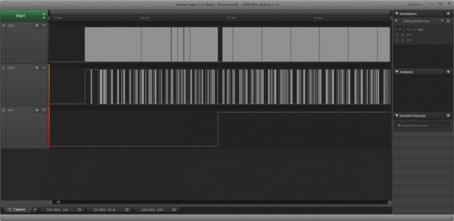
watched rst pin on analyser
plug into usb (no com port shows up)
: rst pin sends every 67 ms a positive pulse
pressing prg button (pc recognized unknown USB devive)
: SWC, SWD, RST lines show behavior as shown in figure

Prog_screenshot.jpg

It seems the bootchip and the K66 are talking
Unfortunately this goes forever

Anything I can try?
Oh, Vin is 4.8 V, 3.3V is 3.3V
An old win xp computer said: unknown USB devce
would a Linux machine behave differently?
 
Try the following: Remove the USB-Cable, press the button, hold it, plug in the cable again, wait a second, then relase the button.
Use a simple blink-sketch
 
I had the same issue one week ago. I was on Win 10, 2 different PC, no way, unrecognized device and no serial port appears.
In the past I've experienced similar issues with 3.2, it was the serial port get stuck, a PC reboot normally fix that, but this time no way, restarting PC was not useful.
At the end I've used my wife Win7, I was very surprised it recognized and was able to program blink led.
Now I'm back to win10 and works ok, dunno what really happen.
 
Last edited:
I've had other Teensy's go 'offline' in what may be a similar way from a 'bad' sketch? They came back when I plugged in a different Teensy - successfully uploaded a sketch to it.

Then with the K66 repeat the 'plug with button down' and see if it shows up to program with a simple blink.

The only reason I 'create' for this is Windows mucked up internally with how a Teensy should be 'treated' after one goes into the weeds. This would perhaps have worked for sumotoy rather than going to another machine that was doing the right thing. Of course if you have a good Old_win_XP machine this should have worked there too, unless it got into the same confused state.
 
Two things, first is just sort of an FYI regarding I2C - it answers a question I had on the LC device a long time back, but I couldn't figure it out. I think the K66 documentation has the answer.

In working on the I2C STOP interrupt for LC I ran across this weird behavior on the I2Cx_FLT register. This is the description from the KL26 doc:
screenshot.550.jpg

For some reason bit4 was toggling and I couldn't figure it out, I even wrote a comment in the i2c_t3 code for it:
Code:
            // There is some weird undocumented stuff going on with the I2C_FLT register on LC.
            // If you read it back, bit4 is toggling, but it is supposed to be part of FLT setting.
            // Writing just the STOPF bit causes things to get stuck, but writing back the read value
            // seems to work

Well now I'm looking at K66, it has this description in the doc:
screenshot.551.jpg

Notice bit4 is STARTF, and it is write-1-clear (which is why writing back the read value worked).

I think this is a documentation error on KL26, and it is probably the same as K66. If so, it's actually lucky this bit didn't cause more problems back when LC came out. I think it is because the enable for it is the same as the STOPF enable (both use SSIE).

===============================================

Second thing, there was previous discussion on I2C and pins. This is what I'm coding for below:
Code:
    //          Interface  Devices     Pin Name      SCL    SDA
    //          ---------  -------  --------------  -----  -----    (note: in almost all cases SCL is the
    //             Wire      All    I2C_PINS_16_17    16     17      lower pin #, except cases marked *)
    //             Wire      All    I2C_PINS_18_19    19     18  *
    //             Wire      3.5    I2C_PINS_7_8       7      8
    //             Wire      3.5    I2C_PINS_33_34    33     34
    //             Wire      3.5    I2C_PINS_40_41    41     40  *
    //            Wire1       LC    I2C_PINS_22_23    22     23
    //            Wire1    3.1/3.2  I2C_PINS_26_31    26     31
    //            Wire1    3.1/3.2  I2C_PINS_29_30    29     30
    //            Wire1      3.5    I2C_PINS_37_38    37     38
    //            Wire2      3.5    I2C_PINS_3_4       3      4
    //            Wire3      3.5    I2C_PINS_42_43    42     43

Now regarding pins 40-43, I'm using the "TBD" info given in post #3. I'm just planning that these will be SMT pads. I've noticed these pads are undefined in core_pins.h at the moment (as expected, given TBD), but it's difficult to code against it when missing.

So given that I'm currently building a list of missing defines (there is also stuff I want to add to kinetis.h). Regarding that I can either generate a pull request, or just post them here, let me know what is preferred.
 
Pull requests are best for specific changes, especially additions to kinetis.h.

I've fallen behind over the last week while struggling with USBHS and Ethernet... but will get caught up soon.
 
Yup, since #569, I got ping and MDIO working. I'm pretty sure the ping replies have wrong checksums, but my Linux machine doesn't seem to mind. On MDIO, I only read the PHY's ID registers.
The checksum field of ICMP echo/reply messages is supposed to be 0, so your changes to the request packet to create the reply maintained that field. You commented out the TACC setting that would have enabled automatic checksum calculation/insertion. However, due to the wimpy TCP/IP checksum algorithm (half-words can be re-ordered and sum will be the same), the IP header checksum will still be correct for your reply packet. ;)

FWIW, below are some of the ethernet registers for the mbed K64 with running Ethernet
Code:
ENET->PALR 0x4e408c86
ENET->PAUR 0xfed8808
ENET->EIR 0x4800000
ENET->EIMR 0xa000000
ENET->ECR 0xf0000112
ENET->MSCR 0x32
ENET->MRBR 0x600
ENET->RCR 0x5f28124
ENET->TCR 0x4
ENET->TACC 0x1
ENET->RACC 0xc0
ENET->MMFR 0x607a0136
it's using 1522 byte packet buffers (ENET RING: 16 Rx, 8 Tx), zero-copy with lwIP PBUFs
 
Last edited:
Tested DHT22 Humidity/temp sensors using the adafruit library with sensor powered from 3.3V with no issues on it's unique single pin interface, ditto the adafruit library for Nokia 5110 LCDs using bit banged SPI. Am having trouble with audio, analog write to the DAC pin numbers works but I think I've missed something on how to specify which of the two DAC channels to drive with the audio library. Is that somewhere in this thread?
 
An old win xp computer said: unknown USB devce
would a Linux machine behave differently?

Update,
I tried on another XP machine, but no success, says unknown device

Could not test on Ubuntu as that verson is too old (e.g. no xy-utility for arduino and off network)
Also could not find the different instructions by Paul scattered around on this forum to debug LINUX (see if HID devices etc, also did not use Linux for the last 10 years or so, so my knowledge is nearly all gone)

If Paul, after looking to the figures I showed earlier, feels that both devices are active, then I may get me a swd programmer and try programming K66 directly.
Any suggestion on SWD programming?
 
If you have an Raspberry PI, you might try installing Arduino for ARM... Probably won't behave much different, but you never know...

Also I am pretty sure you are already doing so, but just in case, you removed everything plugged into the board, including all any IO pins, SDCard, ... Also you have tried different USB cables... I had a point maybe a week ago, where it did not want to program, but it was cleared, when I rebooted and also like some others, I think I may have in between programmed a T3.2...

I have in fact an RPI (B), I may try.
otherwise: all wires disconnected, with/without led-board, reprogrammed on same port T3.2.
I note that RST is going high, SWC/SWD is continuously active (but we do not know what exactly the bootloader chip does, so I do not know if this continuous activity is good or bad)

Maybe I take this as hint (from oute space) to continue with T3.2.
 
If Paul, after looking to the figures I showed earlier, feels that both devices are active, then I may get me a swd programmer and try programming K66 directly.

Please do not do this. If the problem doesn't magically resolve itself when you use other computers, please send the whole thing back to us. I'd like to work with it here, while it's still in this mysterious state.
 
Two ethernet boards are ready to ship on Tuesday (July 5th). One is going to manitou. Who should get the 2nd one? Now's the time to request it. ;)

Like all this K66 beta test stuff, the people eligible are listed in msg #1. There no charge and PJRC pays for shipping. If outside the USA, you'll need to pay any tax+fee the carrier charges when the package arrives.

A third board will (hopefully) be ready by the end of this week. I had a problem with one of the chips and couldn't get the 3rd board built. More chips are on order from Digikey. Parts for 12 more after these first 3 are also on order. Should be 2-3 weeks, depending on OSH Park.

Please understand there isn't much software support for this hardware. Freescale and mBed might have some code, and there's the test program I recently wrote which responds to arp & ping.

https://github.com/PaulStoffregen/k66_ethernet/blob/master/k66_ethernet.ino

Please only request these early ethernet boards if you have the time, ability & desire to play with very low-level ethernet code.
 
Good News. I just did a test with openGLCD. Since the board is not recognized, opgnGLCD drops into a "corecode" mode which is supposed to work on any board.
And it worked "out of the box" on the K66 board using TeensDuino 1.29-beta3 and the Teensy 3.5 board.
It passed full diags (writes and reads to ks0108 RAM) at 96Mhz and 180Mhz.
Performance is actually very good, even without using optimized nanosecond delays (corecode mode can't do delays less than 1 us).
This was done using a voltage shifter.
I haven't looked at the k66 specs yet to see if in line resistors can be used to "cheat" on this part like some of the other 3v Teensy boards.

Now to go in and add tweaks to the library to make it better.
But really good news that it works "out of the box" with the existing OpenGLCD code with no modifications.

--- bill
 
I'm attaching an updated i2c_t3 library (.cpp and .h files). Assuming no bugs, this can drive all buses and pins on T3.5 (including the 4th bus, which as yet is TBD as noted in post #3).

So far I've only barely tested it - just on Wire and Wire2 (I2C0 and I2C2), but it does appear to be working in all Master modes (IMM, ISR, DMA). I haven't tested Slave mode yet (but I did pull in a recent Slave fix on LC). These numbers seem to agree with 3.1/3.2 behavior:
Code:
---------------------------------------------------------
Test5 : Rate adjustment tests.  This sweeps the I2C rates
        on both Master and Slave and times the duration 
        of a 256 byte transfer at each rate.
---------------------------------------------------------
Mode:IMM    Pins:3/4 256 byte transfer at 10000 Hz     (Actual Rate (Hz): 15625) : 163067 us : I2C waiting, no errors
Mode:IMM    Pins:3/4 256 byte transfer at 100000 Hz     (Actual Rate (Hz): 104166) : 23727 us : I2C waiting, no errors
Mode:IMM    Pins:3/4 256 byte transfer at 200000 Hz     (Actual Rate (Hz): 208333) : 13175 us : I2C waiting, no errors
Mode:IMM    Pins:3/4 256 byte transfer at 300000 Hz     (Actual Rate (Hz): 312500) : 9423 us : I2C waiting, no errors
Mode:IMM    Pins:3/4 256 byte transfer at 400000 Hz     (Actual Rate (Hz): 416666) : 7448 us : I2C waiting, no errors
Mode:IMM    Pins:3/4 256 byte transfer at 600000 Hz     (Actual Rate (Hz): 625000) : 5566 us : I2C waiting, no errors
Mode:IMM    Pins:3/4 256 byte transfer at 800000 Hz     (Actual Rate (Hz): 833333) : 4506 us : I2C waiting, no errors
Mode:IMM    Pins:3/4 256 byte transfer at 1000000 Hz     (Actual Rate (Hz): 1000000) : 3893 us : I2C waiting, no errors
Mode:IMM    Pins:3/4 256 byte transfer at 1200000 Hz     (Actual Rate (Hz): 1250000) : 3530 us : I2C waiting, no errors
Mode:IMM    Pins:3/4 256 byte transfer at 1500000 Hz     (Actual Rate (Hz): 1500000) : 3233 us : I2C waiting, no errors
Mode:IMM    Pins:3/4 256 byte transfer at 1800000 Hz     (Actual Rate (Hz): 1875000) : 2939 us : I2C waiting, no errors
Mode:IMM    Pins:3/4 256 byte transfer at 2000000 Hz     (Actual Rate (Hz): 2000000) : 2870 us : I2C waiting, no errors
Mode:IMM    Pins:3/4 256 byte transfer at 2400000 Hz     (Actual Rate (Hz): 2500000) : 2666 us : I2C waiting, no errors
Mode:IMM    Pins:3/4 256 byte transfer at 2800000 Hz     (Actual Rate (Hz): 3000000) : 2566 us : I2C waiting, no errors
Mode:IMM    Pins:3/4 256 byte transfer at 3000000 Hz     (Actual Rate (Hz): 3000000) : 2565 us : I2C waiting, no errors
Mode:ISR    Pins:3/4 256 byte transfer at 10000 Hz     (Actual Rate (Hz): 15625) : 163064 us : I2C waiting, no errors
Mode:ISR    Pins:3/4 256 byte transfer at 100000 Hz     (Actual Rate (Hz): 104166) : 23729 us : I2C waiting, no errors
Mode:ISR    Pins:3/4 256 byte transfer at 200000 Hz     (Actual Rate (Hz): 208333) : 13184 us : I2C waiting, no errors
Mode:ISR    Pins:3/4 256 byte transfer at 300000 Hz     (Actual Rate (Hz): 312500) : 9385 us : I2C waiting, no errors
Mode:ISR    Pins:3/4 256 byte transfer at 400000 Hz     (Actual Rate (Hz): 416666) : 7450 us : I2C waiting, no errors
Mode:ISR    Pins:3/4 256 byte transfer at 600000 Hz     (Actual Rate (Hz): 625000) : 5564 us : I2C waiting, no errors
Mode:ISR    Pins:3/4 256 byte transfer at 800000 Hz     (Actual Rate (Hz): 833333) : 4508 us : I2C waiting, no errors
Mode:ISR    Pins:3/4 256 byte transfer at 1000000 Hz     (Actual Rate (Hz): 1000000) : 3892 us : I2C waiting, no errors
Mode:ISR    Pins:3/4 256 byte transfer at 1200000 Hz     (Actual Rate (Hz): 1250000) : 3530 us : I2C waiting, no errors
Mode:ISR    Pins:3/4 256 byte transfer at 1500000 Hz     (Actual Rate (Hz): 1500000) : 3234 us : I2C waiting, no errors
Mode:ISR    Pins:3/4 256 byte transfer at 1800000 Hz     (Actual Rate (Hz): 1875000) : 2941 us : I2C waiting, no errors
Mode:ISR    Pins:3/4 256 byte transfer at 2000000 Hz     (Actual Rate (Hz): 2000000) : 2867 us : I2C waiting, no errors
Mode:ISR    Pins:3/4 256 byte transfer at 2400000 Hz     (Actual Rate (Hz): 2500000) : 2662 us : I2C waiting, no errors
Mode:ISR    Pins:3/4 256 byte transfer at 2800000 Hz     (Actual Rate (Hz): 3000000) : 2569 us : I2C waiting, no errors
Mode:ISR    Pins:3/4 256 byte transfer at 3000000 Hz     (Actual Rate (Hz): 3000000) : 2566 us : I2C waiting, no errors
Mode:DMA[0] Pins:3/4 256 byte transfer at 10000 Hz     (Actual Rate (Hz): 15625) : 163059 us : I2C waiting, no errors
Mode:DMA[0] Pins:3/4 256 byte transfer at 100000 Hz     (Actual Rate (Hz): 104166) : 23727 us : I2C waiting, no errors
Mode:DMA[0] Pins:3/4 256 byte transfer at 200000 Hz     (Actual Rate (Hz): 208333) : 13179 us : I2C waiting, no errors
Mode:DMA[0] Pins:3/4 256 byte transfer at 300000 Hz     (Actual Rate (Hz): 312500) : 9400 us : I2C waiting, no errors
Mode:DMA[0] Pins:3/4 256 byte transfer at 400000 Hz     (Actual Rate (Hz): 416666) : 7451 us : I2C waiting, no errors
Mode:DMA[0] Pins:3/4 256 byte transfer at 600000 Hz     (Actual Rate (Hz): 625000) : 5564 us : I2C waiting, no errors
Mode:DMA[0] Pins:3/4 256 byte transfer at 800000 Hz     (Actual Rate (Hz): 833333) : 4504 us : I2C waiting, no errors
Mode:DMA[0] Pins:3/4 256 byte transfer at 1000000 Hz     (Actual Rate (Hz): 1000000) : 3889 us : I2C waiting, no errors
Mode:DMA[0] Pins:3/4 256 byte transfer at 1200000 Hz     (Actual Rate (Hz): 1250000) : 3530 us : I2C waiting, no errors
Mode:DMA[0] Pins:3/4 256 byte transfer at 1500000 Hz     (Actual Rate (Hz): 1500000) : 3233 us : I2C waiting, no errors
Mode:DMA[0] Pins:3/4 256 byte transfer at 1800000 Hz     (Actual Rate (Hz): 1875000) : 2941 us : I2C waiting, no errors
Mode:DMA[0] Pins:3/4 256 byte transfer at 2000000 Hz     (Actual Rate (Hz): 2000000) : 2865 us : I2C waiting, no errors
Mode:DMA[0] Pins:3/4 256 byte transfer at 2400000 Hz     (Actual Rate (Hz): 2500000) : 2664 us : I2C waiting, no errors
Mode:DMA[0] Pins:3/4 256 byte transfer at 2800000 Hz     (Actual Rate (Hz): 3000000) : 2568 us : I2C waiting, no errors
Mode:DMA[0] Pins:3/4 256 byte transfer at 3000000 Hz     (Actual Rate (Hz): 3000000) : 2570 us : I2C waiting, no errors
I2C waiting, no errors

There is a hidden change in that the code that sets the rate dividers is completely replaced, and it is now possible to specify bus freq in Hz directly (I2C_RATE_xxx enums still work but they are not required). This was done to eliminate the need to create divide tables for specific bus freqs. In the above table, "transfer at X" is the target rate, and "Actual Y" is the closest calculated rate given the divide table limits.

So far the 3MHz rate is max given the bus max freq of 60MHz. I tried testing some overclock bus speeds (eg. 80M, 120M) but they would not compile, and I did not investigate why, so for now I've only tested to 60MHz F_BUS.

This should compile as-is, but there are some defines at the top of the header which will eventually move into other files (kinetis.h, core_pins.h).

This is the pin list:
Code:
    //          Interface  Devices     Pin Name      SCL    SDA
    //          ---------  -------  --------------  -----  -----    (note: in almost all cases SCL is the
    //             Wire      All    I2C_PINS_16_17    16     17      lower pin #, except cases marked *)
    //             Wire      All    I2C_PINS_18_19    19     18  *
    //             Wire      3.5    I2C_PINS_7_8       7      8
    //             Wire      3.5    I2C_PINS_33_34    33     34
    //             Wire      3.5    I2C_PINS_40_41    41     40  *
    //            Wire1       LC    I2C_PINS_22_23    22     23
    //            Wire1    3.1/3.2  I2C_PINS_26_31    26     31
    //            Wire1    3.1/3.2  I2C_PINS_29_30    29     30
    //            Wire1      3.5    I2C_PINS_37_38    37     38
    //            Wire2      3.5    I2C_PINS_3_4       3      4
    //            Wire3      3.5    I2C_PINS_42_43    42     43

As I understand it, all these pins are 3.3V, is that right?
 

Attachments

  • i2c_t3.cpp
    76.9 KB · Views: 105
  • i2c_t3.h
    52 KB · Views: 108
nox771,
It is hard to tell from that table how the requested bit rate maps to an actual SCL bit rate. I'm assuming that the table above is a bit backwards.
In other words, the "Actual Rate" column is showing the SCL rate that would need to be requested/set to get the data bit rate in the first column.
It would seem better to show the requested SCL bit rate and then the actual measured bit rate using a logic analyzer.
i.e. if I do a Wire.setClock(hz) what is the actual SCL bit rate on the bus?
I would expect the actual SCL bit clock rate to always be equal to or less than what is requested.
 
nox771: - I pulled your latest code and tested at 180MHz, then dropped to 96MHz - same result at both speeds :: Fails on Wire2
First ODD thing - if I do the following on Wire1 with no display the code runs through this, if I have the display on or not Wire2 acts that same? BTW this is the same result I got from my hacked version of i2c_T3.

I wrote most of the following using the Adafruit driver code - then went to this modified version of SCANNER :: View attachment scanner.ino
The results are the same - but a more generic test - the output below will be updated from running scanner.

In the attached scanner change which Wire# is commented out (line 17 or 18) to jump the bus# and pin selection together.

When I do this with Wire1 my 1306 (at address 0x3c) display works. When changed as above to use Wire2 it fails.

I traced it as far as this - it is stuck in the with 0==timeout in "while(!done_(i2c) ..." on the first Wire.endTransmission():

To get output - Here is how I modified done_ and finish_, in done_ the currentStatus stays at 1 with wire2, on wire1 it goes to 5 and exits the while and prints "C" and returns through endTransmission and continues to bring up the display.
Code:
#define tprint(a, b) { Serial.print(a); Serial.println(b);}
uint8_t i2c_t3::done_(struct i2cStruct* i2c)
{
	static uint32_t once = 0xfff;
	if ( 0xfff==once || once!=i2c->currentStatus ) {
		once=i2c->currentStatus;
	  tprint("done_  currentStatus::", i2c->currentStatus );
	}

Code:
uint8_t i2c_t3::finish_(struct i2cStruct* i2c, uint8_t bus, uint32_t timeout)
{
    elapsedMicros deltaT;
	  tprint("finish_ ::", "A" );

    // update timeout
    timeout = (timeout == 0) ? i2c->defTimeout : timeout;
	  tprint("finish_ ::", "B" );

    // wait for completion or timeout
    deltaT = 0;
    [B]while(!done_(i2c) && (timeout == 0 || deltaT < timeout));
	  tprint("finish_ ::", "C" );[/B]

This is my full trace log to get there on Wire2::
Hello World
Hello World wb
---------------------------------------------------
Starting scan...
endTransmission currentPins I2C_PINS_3_4::0
endTransmission bus::2
endTransmission sendStop::1
endTransmission timeout::0
endTransmission :: sendTransmission_
finish_ ::A
finish_ ::B
done_ currentStatus::1

If I return the scanner to Wire1 I get this trace showing it gets done_ and leaves the while back to scanner for "ACK":
Hello World
Hello World wb
---------------------------------------------------
Starting scan...
endTransmission currentPins::not I2C_PINS_3_4
endTransmission bus::1
endTransmission sendStop::1
endTransmission timeout::0
endTransmission :: sendTransmission_
finish_ ::A
finish_ ::B
done_ currentStatus::1
finish_ ::C
endTransmission :: timeout
Addr 0x3C ACK
 
nox771,
It is hard to tell from that table how the requested bit rate maps to an actual SCL bit rate. I'm assuming that the table above is a bit backwards.
In other words, the "Actual Rate" column is showing the SCL rate that would need to be requested/set to get the data bit rate in the first column.
It would seem better to show the requested SCL bit rate and then the actual measured bit rate using a logic analyzer.
i.e. if I do a Wire.setClock(hz) what is the actual SCL bit rate on the bus?
I would expect the actual SCL bit clock rate to always be equal to or less than what is requested.

No it is the correct order. If I request 2.8M rate, and I am using a 60M bus, it would require a divider of 21.43 (as an integer calc it is a divide ratio of 21). However there is no divide ratio of 21, there is only 20 or 22. The algorithm errs on the lower ratio (higher freq) side as the throughput rate is severely limited at the high end (this could be done either way, either rounding up or down). So in this case it would choose 20, yielding a 3M setting. So requesting 2.8M in this case will yield a 3M rate.

That's all theoretical rates. On a logic analyzer the rates run a little slow IIRC due to overhead. And in a throughput sense it is much lower, especially at the high end. At high freq the throughput becomes dominated by the "gaps" between bytes, which are caused by peripheral and ISR processing latency (I2C traffic does not have an unbroken clock, there is usually a turnaround delay after the ACK cycle) . I don't have any logic analyzer plots yet to pair up against the settings.
 
I'll think about it, but usually this (below) is caused by a wiring error. Pullups not right, cross-wired, etc... I would check connectivity first.

I traced it as far as this - it is stuck in the with 0==timeout in "while(!done_(i2c) ..." on the first Wire.endTransmission():
 
I'll think about it, but usually this (below) is caused by a wiring error. Pullups not right, cross-wired, etc... I would check connectivity first.

I've checked and counted and reversed the wires at 3&4. As noted - I can pull the display off Wire1 and get a timeout - I still hang with Wire2?

I put this ONCE item in to stop the repeated calls during wait from spewing until the completion. I just edited that to confirm it just returns 1 forever on Wire2.
 
Status
Not open for further replies.
Back
Top