K66 Beta Test

Status
Not open for further replies.
@Ben - that is a cool card image / data collection!

As I noted before and tried to do in the Post_8 image of my early card - I like having a tenth inch index to hold up to these things.

In working with 24 pins it is hard to count pins with no room for silkscreen on top - so far the wrong wire on the wrong pin has only cost me time.

Seeing the teensy TEENSY 3.2 on my desk it is easy to see why - you can more easily count 7 pins from either to check and double check. Having the tenth inch scale card with pin numbers makes placement and confirmation easy. I tried to do that with yours and didn't get there right away in excel. I'll have to work on that again on a business card maybe.
 
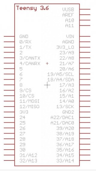
Ok guys this is my prelim eagle footprint, some of the pin functions could be wrong (after #39 they are not confirmed with a pin out card), I left out the alternate pins because there are so damn many of them that its hard to put them all on the symbol. I have not updated this other then to add a warning since last week, I have a lot of catching up to do IRL.

Guys as we find things out let me know and I will gladly update the footprint. The 3.5 footprint should not be to hard I think it will mainly be fewer functions on pins and 5V tolerance.


Prelim!!! Check all PIN Assignments!!!!
Pins after #39 have not been confirmed
as to functions, alternate pin functions not
marked.


View attachment 7903

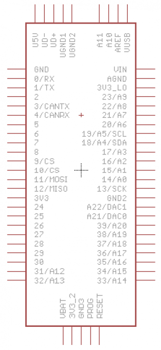
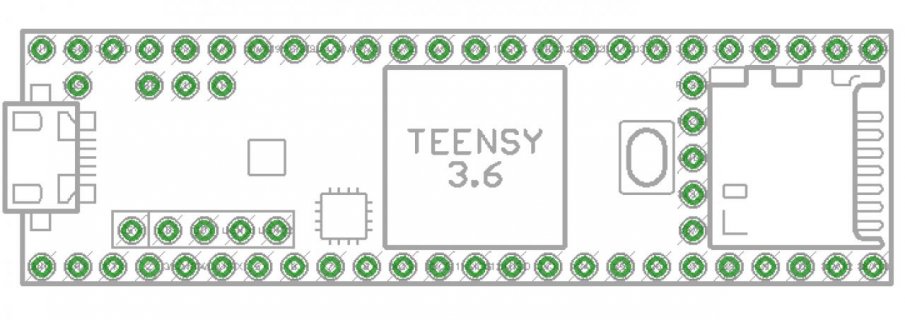
Footprint and symbol screenshots for those who don't have eagle or aren't around a computer to look.
Note!!! 3.18mm is actually 3.175mm for the second USB, eagle rounded it
I also have an updated version I am working on.

View attachment 7904
View attachment 7905

Hi Donziboy2 - Thanks for providing this! Is the download from this post the most recent version? I want to make a PCB board that breaks out all the signals to terminal blocks for easy connecting.

Thanks!
Brent
 
T_3.6 EEPROM write in HSRUN sketch via SNOOZE

UPDATE: After going to the trouble of writing post 1325 I figured I should try it. I pulled down duff2013/Snooze_V6_Beta

THIS WORKS - it has been tested only as far as seeing the code below work. I have not read anything about SNOOZE (there are pretty pictures in the README.md), just opened the SIMPLE sample and put in some EEPROM[] array read writes.

The code below is the main code to replace that in " {sketchbook}\libraries\Snooze_V6\examples\REDUCED_CPU_BLOCK\simple", you'll need the other two DUFF files in that sample.

@DUFF : Good Work!
> All I had to Add was to EXIT and RESUME HSRUN, even when it was at 2MHz with HSRUN set the write failed.
> Is there a way to set to other than 2 MHz or is that a magic value?
> Is there a single hunk of code to extract to perform your magic for this 'special case'?
> Is the world really unsafe at this point - supposing anything time based was in use ( SPI, SDHC, I2C, USB, Ethernet, ...)

@WORLD :
> I have no idea of the state of the TEENSY after this is done. Are we safely back on 'terra firma' or if after this is done a RESET should be done?
> This confirms that EEPROM read works even at HSRUN

What the sketch does:: For DEBUG I just blink the LED as I do a test READ / WRITE / READ of 10 EEPROM values.:
> When a Flash read of a value doesn't match the TestVal you get a 250ms on/off, otherwise darkness (run it twice in a row values will match here)
> delay(1250);
> When a FLASH WRITE is done a quick 50ms on/off appears
> delay(1000);
> If write worked you see darkness, otherwise When a Flash read of a value doesn't match the TestVal you get a 250ms on/off
> LED turns ON and test is over
> delay(2000);
> If SNOOZE was used and HSRUN cycled OFF/ON then the LED does a fast blink

Seeing it yourself - read and write TestVal to 10 EEPROM locations at any compile speed:
> Set "const byte TestVal = 8;" to a BYTE value of your choice
> Set "const byte StartLoc = 3400;" to an EEPROM address 0 to 3089
> To see it fail on a T_3.6 over 120 MHz, comment out the line: "DoSnooze = 1;"

Code:
/***************************************
   REDUCED_CPU_BLOCK allows you to run
   code at 2 MHz (VLPR). See micro_lp and
   delay_lp to see how to convert core
   functionality at F_CPU to work at 2 MHz.
 ****************************************/
#include <EEPROM.h>
#include <Snooze.h>
#include "delay.h"

// REDUCED_CPU_BLOCK needs a SnoozeBlock passed to it
// so we pass a dummy SnoozeBlock with no Drivers installed.
SnoozeBlock dummyConfig;

const byte TestVal = 12;
const byte StartLoc = 2200;
bool DoSnooze = 0;

void setup() {
  pinMode(LED_BUILTIN, OUTPUT);

  TestFlash(); // Test Read Flash at F_CPU
  delay(1250);               // wait for a second
#if defined(__MK66FX1M0__)
#if F_CPU > 120000000
  DoSnooze = 1;
#endif
#endif
  if ( DoSnooze ) {
    REDUCED_CPU_BLOCK(dummyConfig) {
      SMC_PMCTRL = SMC_PMCTRL_RUNM(0); // EXIT HSRUN mode
      while (SMC_PMSTAT == SMC_PMSTAT_HSRUN) ; // wait for !HSRUN
      WriteFlash();
      SMC_PMCTRL = SMC_PMCTRL_RUNM(3); // enter HSRUN mode
      while (SMC_PMSTAT != SMC_PMSTAT_HSRUN) ; // wait for HSRUN
    }
  }
  else
    WriteFlash();
  delay(1000);               // wait for a second

  TestFlash(); // Test Read Flash at F_CPU
  digitalWrite(LED_BUILTIN, HIGH);   // turn the LED_BUILTIN on (HIGH is the voltage level)
  delay(2000);               // wait 2 seconds
}


void loop() {
  if ( DoSnooze ) {
    QuickBlink(); // Now may be a good time to leave
  }
}

void   TestFlash() {
  for ( int ii = StartLoc; ii < StartLoc + 10; ii++ ) {
    if ( TestVal != EEPROM[ ii ] ) {
      digitalWrite(LED_BUILTIN, HIGH);   // turn the LED_BUILTIN on (HIGH is the voltage level)
      delay(0250);               // wait for a second
      digitalWrite(LED_BUILTIN, LOW);    // turn the LED_BUILTIN off by making the voltage LOW
      delay(0250);               // wait for a second
    }
  }
}

void WriteFlash() {
  for ( int ii = StartLoc; ii < StartLoc + 10; ii++ ) {
    EEPROM[ ii ] = TestVal;
    QuickBlink();
  }
}

void QuickBlink() {
  for ( int8_t ii = 0; ii < 2; ii++ ) {
    digitalWrite(LED_BUILTIN, (ii % 2));
    if ( DoSnooze )
      delay_lp(50);    // wait for a second
    else
      delay(50);
  }
}

BTW: I did this with TD_1.30 release version on IDE 1.6.11 and the current SNOOZE_v6_Beta on my T_3.6 beta 3 board. Also compiled for T_3.5 at 168 MHz and the #ifdef kept it from using snooze as it isn't needed on T_3.5 as it doesn't have the HSRUN high voltage switchover that blocks EEPROM write like the T_3.6.

Posted on hopefully the right thread for DUFF to offer any insight on this SNOOZE case
 
Last edited:
Teensy 3.5 Card: "Do not apply more than 5 volts to A10, A11, A21, A22, A25, A26, AREF, Program or Reset".

Did you really mean to say 5 V here, or 3.3V ? If the card is correct, what is the voltage limit on the other pins?

Paul - the vBat - or "Vb" pin should be in that list as well on the T_3.5
 
Hi Donziboy2 - Thanks for providing this! Is the download from this post the most recent version? I want to make a PCB board that breaks out all the signals to terminal blocks for easy connecting.

Thanks!
Brent

Nope, that one needed some updates based on Pauls cards. Below is the latest.

View attachment Teensy_3_6.zip

edit..
I also removed the old file from my previous post so it does not get used by mistake.
 
Last edited:
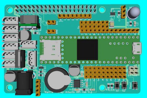
For the fun of it, just starting to play around with my Hat board (that could plug into RPI or Odroid or UP board), to use either the T3.5 or T3.6. Right now just playing around with ideas.

So far I dropped the BNO055 IMU plugging directly into board... I also changed Sound from using simple transistor RC circuit to try out using a simple AMP setup like LM483, with real simple speaker. Still have Neopixel, but may change?

Still want to hook up more configuration/communication options between Main board and Teensy. Like using more shunts to hook up UART between the two (actually still there). But also add ability to connect SPI between the two and maybe I2C...

Right now just getting ideas of space.

T3.6-RPI-Hat.jpg

For example do I try to add space to back to Teensy for SDCard insertion. Or maybe mount Teensy high enough to go over top of connectors when no wires are connected...

Will create a new thread if/when this goes somewhere.

Kurt
 
Hi all,


Here are a couple of Eagle devices for 3.5/3.6.

Let me know if anyone has any thoughts on improvements etc

I've listed the different pins but only the primary ones —*for instance only the first channel of SPI and I2C etc — I figure this means you can put it in to Eagle and connect basic stuff up without consulting any board.

Disclaimer — it is totally 100% untested — use with caution!

Moved the file to here: https://github.com/jamescarruthers/Eagle


James

Screen Shot 2016-09-09 at 22.38.46.jpgScreen Shot 2016-09-09 at 22.39.04.jpgScreen Shot 2016-09-09 at 22.38.26.pngScreen Shot 2016-09-09 at 22.38.33.jpg
 
Last edited:
@Kurt - did you see this thread: Dual-channel-16bit-dac-PT8211 - would this give you help on the sound?
Thanks,

That might be fun, but probably not enough room for two speakers. You probably can not tell in the picture. The component toward the bottom sort of below SDCard is a speaker. For sound, thinking along the line of the propshield. Thought of using same circuit but that chip is probably to small for me to solder. Although for this board may experiment and have some of it preassembled.
 
KurtE, in terms of communications, it might be useful to have for the 3 main serial ports, the main CTS pin (and perhaps another pin for RTS). I picked up an Adafruit BLE board, and it wants CTS/RTS connected.

For i2c, consider having an option to connect pull-up resistors. It also would be useful to have several parallel rows, so that you could easily attach several i2c devices to the same chain.

For spi, consider also having several parallel rows, with the various CS<x> pins, so you could more easily plug in two different SPI devices on the same SPI bus.

Have two or three places you can add a push button. I used to use pin #2 for the generic push button, but now I use pin #3, since it isn't used by the prop-shield, audio shield, and the feather/OLED shield has a button for pin 3.

I think you now have a 2.1mm power jack. It may be useful to have a JST/charger option. The Adafruit Pro Trinket Lilion/Lipoly backpack is perhaps the easiest to use for through hole soldering (https://www.adafruit.com/products/2124). One thing that it would be very useful to have is the ability to switch power sources and cut off the power (this requires the user to cut the pad between Vusb and VIN).
 
Hi all,


I just wanted to share this —*it's the full pin device for Eagle.

I'm going to make a simplified version too — without the USB host and middle row of pins.

Disclaimer — it is totally 100% untested —*use with caution!


James

Do one without the USB host. I think it's designed for the usb connector to plug into the top of the board.
 
Paul, can you say some words regarding your plans for SD-card support ?

Do you mean something other than "behind schedule" or "really wanted to do this last week, but Kickstarter..."

My current plan is to adapt the single sector polled code as a short-term solution to get the Arduino SD library working. I want to define some name like SDIO_PORT to be used with SD.begin(pin), to tell the SD lib to use the native SDIO instead of SPI with a chip select pin. Maybe "SDIO_PORT" is too generic? But something too long might be more trouble than it's worth. Open to suggestions on good names...

Long-term, I want to do much more work on the optimized SD code I started earlier this year. Much work remains to add writing support. I also want to extend it to use 2K or 4K or maybe even 8K multi-sector reads & writes, and to speculatively pre-cache files using DMA and interrupts when there aren't requests from the library for reads or writes.
 
Hardcoded Speed Drop and Resume from 180 Mhz to 120 Mhz to allow EEPROM writes that work. A clumsy cut and paste of stuff that seemed important looking from mk20dx128.c. The writes worked, but USB goes away and stays there. I'd call the resume a failure so far. I'll start a thread later to show the code for feedback.

100 writes with no value change takes 47 micros, with values changing takes 43,460 micros { Tested at 120 where I can print }
So writing all 4KB could take almost 1.8 seconds { using simple byte array access }
 
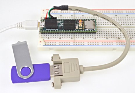
I don't see why you wouldn't break that out to socket? Or are the pins not the standard 0.1"?

They are .1", but they aren't on the same grid as the rest of the board (they are offset .05").
The white line around the holes usually means a connector is plugged into the top.
And there's this picture.
usb.jpg
 
They are .1", but they aren't on the same grid as the rest of the board (they are offset .05").
The white line around the holes usually means a connector is plugged into the top.
And there's this picture.
View attachment 8105

Totally — and it makes total sense when it's on a breadboard — but this is for an Eagle device.

Assuming the USB host will do midi at some point I already have an idea for something I want to make whereby breaking out those to a USB connector will be needed.
 
Teensy 3.6 Breakout to screw terminal board

Below is an attachment for an Eagle Teensy 3.6 breakout board based on Donziboy2's part. It breaks out every single connection to a screw terminal and provides multiple 3.3V and GND connections. If anyone has some time to take a look and provide feedback it would be much appreciated. :) This is only my second board and the first one was 3 years ago. I have triple checked the connections with the printed card and verified that it looks good at oshpark.com so hopefully its in good shape but would be great to have an experienced pair of eyes take a look.

Thanks!
Brent

[Edit: Updated the top silk screen to not suck]
 

Attachments

  • Teensy36IO.zip
    248.3 KB · Views: 639
Last edited:
Status
Not open for further replies.
Back
Top