
Hi all!
My setup: Teensy 3.2 @ 96MHz. I wanted to setup a Timer interrupt whose interval would vary -- whenever the interrupt fires, I wish to change the Timer period. I've used the TimerOne library to do this on an Arduino Uno (16MHz). The code ran as expected, on the teensy however it did not.
I've only just started working with a teensy, so either I don't understand how to use TimerOne to do this OR TimerOne does not support this at all.
Here's the code:
Run the code as is first. Then uncomment either setPeriod() or the FTM1_MOD direct access -- in both cases the mainloop would show that the MOD is updated but the micros() print-out or a scope would tell you that it didn't work.
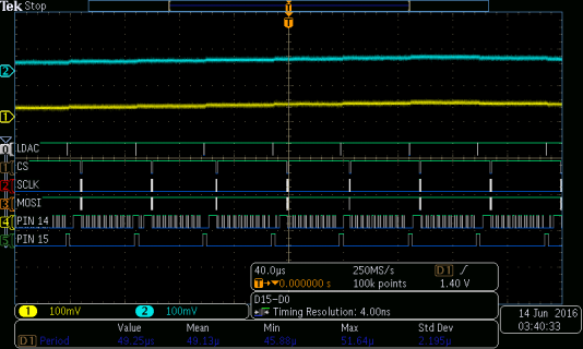
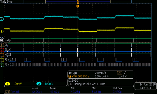
It seems MOD is updated, with the correct value too; but the interrupt triggers at the wrong time. I do not understand why. See attached photos.
In both images, the timer is initialized to 50us. Please ignore other signals, they don't matter. Pin 15 is toggled by the ISR function, so we can "see" the ISR active. When I comment setPeriod(), the ISR fires every 50us as expected. With setPeriod uncommented, the interrupt seems to be firing fast, at 5us. I tried different initial timer periods but the ISR still fired @ 5us, ie, ther's no correlation between the 50us and 5us.
Possible Work-around
I delved into the K20 data sheet and also this very useful Application Guide on FlexTimer. The guide has C programs on synchronous PWM updates and details on how to synchronise the MOD update (hardware and software triggers). After wrapping my head around the terminology and the vast configuration options available, I realised many things:
I don't know why TimerOne (default) legacy synchronisation failed.
@Paul Did you intend to support this use case? IMO, it will be difficult to simply integrate this because of the CPWM conflict.
PS I've also tried calling setPeriod outside the ISR function with same problem. I can post the code upon request.
Thanks,
Ananya
My setup: Teensy 3.2 @ 96MHz. I wanted to setup a Timer interrupt whose interval would vary -- whenever the interrupt fires, I wish to change the Timer period. I've used the TimerOne library to do this on an Arduino Uno (16MHz). The code ran as expected, on the teensy however it did not.
I've only just started working with a teensy, so either I don't understand how to use TimerOne to do this OR TimerOne does not support this at all.
Here's the code:
Code:
#include <TimerOne.h>
void setup(void)
{
  pinMode(13, OUTPUT);
  pinMode(15, OUTPUT):
  Timer1.initialize(9000);
  Timer1.attachInterrupt(blinkLED);
  Serial.begin(115200);
}
// The interrupt will blink the LED, and
// mainloop will print FTM1 configuration

unsigned long last_event_micros = 0;
volatile uint8_t lstate = 0, wflag = 0;

void blinkLED(void)
{
  digitalWrite(15, HIGH);
  lstate = !lstate;
  wflag = 1;
  digitalWrite(13, lstate);
  /*
  if (lstate == 0){
    FTM1_MOD = 900;
  }
  else{
    FTM1_MOD = 65000;
  }
  */
  //Timer1.setPeriod(9000);
  digitalWrite(15, LOW);
}

void loop(void)
{
  if (wflag == 1){
    Serial.print(micros() - last_event_micros);
    last_event_micros = micros();
    Serial.print(" ");
    Serial.print(FTM1_MOD);
    Serial.print(" ");
    Serial.println(FTM1_SC & 0x7);
    wflag = 0;
  }
}It seems MOD is updated, with the correct value too; but the interrupt triggers at the wrong time. I do not understand why. See attached photos.
In both images, the timer is initialized to 50us. Please ignore other signals, they don't matter. Pin 15 is toggled by the ISR function, so we can "see" the ISR active. When I comment setPeriod(), the ISR fires every 50us as expected. With setPeriod uncommented, the interrupt seems to be firing fast, at 5us. I tried different initial timer periods but the ISR still fired @ 5us, ie, ther's no correlation between the 50us and 5us.
Possible Work-around
I delved into the K20 data sheet and also this very useful Application Guide on FlexTimer. The guide has C programs on synchronous PWM updates and details on how to synchronise the MOD update (hardware and software triggers). After wrapping my head around the terminology and the vast configuration options available, I realised many things:
- TimerOne does not configure any MOD/CnV synchronisation bits
- According to data sheet sec. 36.4.10.2 MOD register update,
We can see that this indeed happens (serial output shows). But the ISR doen't trigger properly. So, I set FTM_MODE_FTMEN so that MOD sync is now by data sheet sec. 36.4.11.4 (I believe the datasheet is also calling this "enhanced PWM synchronisation" (FTMEN=1, FTM_SYNCONF_SYNCMODE=1) and the other one (which TimerOne uses, by default "legacy synchronisation")register will be updated after counter transitions from MOD to MOD-1. - Now, I depended on the code examples of the Guide document sec 3.11, particularly sec 3.11.3.
- MOD (and CnV) are updated at a "load point" either one of CNTMIN or CNTMAX, (see FTM_SYNC register desc.) TimerOne does not set any "load point" bit.
- The program below works exactly as I wanted it to. I haven't attached scope images for this program. You can even play with the FTM1_SC_PS bits and MOD in the ftm_isr()
Code:volatile uint8_t lstate = 0, wflag = 0; unsigned long last_micros_event = 0; void setup(){ Serial.begin(115200); pinMode(13, OUTPUT); FTM1_SC = 0; FTM1_FMS = 0; FTM1_MODE = FTM_MODE_FTMEN; // WPDIS set, all registers accessible FTM1_SYNC |= FTM_SYNC_CNTMIN; // CNTMIN load point // EDIT 1 ----------------------------------------------------------------------------------- // Enhanced PWM sync, allow software to trigger synch via SWSYNC bit, Reset timer and load MOD as soon as SWSYNC is set by software // don't wait till next loading point. // Naturally, I set the SWSYNC bit in the ISR.. FTM1_SYNCONF |= FTM_SYNCONF_SYNCMODE | FTM_SYNCONF_SWWRBUF [COLOR="#008000"]| FTM_SYNCONF_SWRSTCNT[/COLOR]; // EDIT1 (SWRSTCNT) FTM1_MOD = 60769; FTM1_SC = FTM_SC_CLKS(1) | FTM_SC_PS(7) | FTM_SC_TOIE; NVIC_ENABLE_IRQ(IRQ_FTM1); } void loop(){ if (wflag == 1){ Serial.print(micros() - last_event_micros); last_event_micros = micros(); Serial.print(" "); Serial.print(FTM1_MOD); Serial.print(" "); Serial.println(FTM1_SYNC); wflag = 0; } } void ftm1_isr(){ // EDIT1 ----------------------------------------------------------------------------------- // no need to do FTM1_SC = 0 uint32_t sc = FTM1_SC; if (sc & 0x80) FTM1_SC = (sc & 0x7f); if (lstate){ FTM1_MOD = 65535; } else{ FTM1_MOD = 100; } digitalWrite(13, lstate); lstate = !lstate; wflag = 1; // this tells the synchronisation hardware that CPU has written to MOD buffer. // and asks it to "latch" the buffered value into MOD [COLOR="#008000"]right now because of SWRSTCNT.[/COLOR] FTM1_SYNC |= FTM_SYNC_SWSYNC; } - According to data sheet sec. 36.4.10.2 MOD register update,
- TimerOne works in CPW aligned mode

- That's a good thing because it basically doubles the max. supported period, but.. read on..
- In the code above, the load point is set at CNTMIN. The ISR will fire at CNTMAX (always, no matter what config).
- In CPWM, MOD will be updated (MOD - CNTIN) * timerCLK later. It should have updated ASAP. Setting load point as CNTMAX would be worse, as the update happens 2*(MOD-CNTIN) * timerCLK later, at the next load point -- whereas my application requires it ASAP.
- In non-CPWM, one of the CNTIN or CNTMAX should be set (I have CNTMIN).
OLD: So the MOD is updated right after ISR occurs -- exactly what I need!
EDIT1: Due to the SWRSTCNT bit, the MOD value is loaded when SWSYNC is set, instead of waiting for the loading point that would come after SWSYNC was set. This is important when PS bits are also changed with MOD. Without SWRSTCNT, PS would get updated but MOD would update at next load point, which is atleast (oldMOD - CNTIN)*timerCLK away. See datasheet sec 36.4.11.4 for diagrams and a flowchart for MOD synchronisation.
I don't know why TimerOne (default) legacy synchronisation failed.
@Paul Did you intend to support this use case? IMO, it will be difficult to simply integrate this because of the CPWM conflict.
PS I've also tried calling setPeriod outside the ISR function with same problem. I can post the code upon request.
Thanks,
Ananya
Attachments
Last edited: