newbie needs help on Serial.read ()

Status
Not open for further replies.

fadzil

Member
Hey everyone,

So i have this projects where i should be controlling a BLDC motor wirelessly. I should make it at least start and stop just by entering certain character on the keyboard. BTW, im using the latest Teensyduino and a CC1101. As a newbie, i really dont have any idea except that i send something to the receiver as i have two CC1101, and only after the receiver got the data, the program of my BLDC Motor start to run. But after weeks trying to figure out, i am still lost as the data that received (im using the command of Serial.vailable and Serial.read )is always a -1. Just for starting the motor, i might just use the value of -1. But i cant have any other command as it only have "-1" value regardless of what ever i send on the transmitter.

here is my transmitter code
PHP:
/* Routinen für Teensy  */ 
/* mit Pinning:         */
/* Teensy Pin   CC1101 Funktion  */
/*     6        CS               */
/*    11        MOSI             */
/*    12        MISO             */
/*    14        SCK              */
/*    17        GD0              */
   #include <SPI.h>
   #include "ELECHOUSE_CC1101.h"
   
   #define tx

#ifdef tx
#define size 2
byte TX_buffer[size]={0};
byte i;

void setup()
{  
  Serial.begin(9600);
  
}


void loop()
{
  while (Serial.available()==0);
  int val = Serial.read();
  if (val=='s'){
  ELECHOUSE_cc1101.Init();
  for(i=1;i<size;i++)
  {
     TX_buffer[i]=i;
     
  } 
  ELECHOUSE_cc1101.SendData(TX_buffer,size);
  delay(1);
  Serial.println("starting..");
  }
   while (Serial.available()==0);
  int val = Serial.read();
  if (val=='s'){
  ELECHOUSE_cc1101.Init();
  for(i=1;i<size;i++)
  {
     TX_buffer[i]=i;
     
  } 
  ELECHOUSE_cc1101.SendData(TX_buffer,size);
  delay(1);
  Serial.println("starting..");
  }
 }

#endif

and here is the rx code.
PHP:
#include "bldc_control.h"
#include "I2Cdev.h"
//#include "MPU6050_6Axis_MotionApps20.h"
#include "ELECHOUSE_CC1101.h"
#include <Wire.h>
#include <SPI.h>

#define TASTER 23
#define LED1 13
#define LED2 10


//MPU6050 mpu;
BLDC_Control motor(true);

bool dmpReady = false;  // set true if DMP init was successful
uint8_t mpuIntStatus;   // holds actual interrupt status byte from MPU
uint8_t devStatus;      // return status after each device operation (0 = success, !0 = error)
uint16_t packetSize;    // expected DMP packet size (default is 42 bytes)
uint16_t fifoCount;     // count of all bytes currently in FIFO
uint8_t fifoBuffer[64]; // FIFO storage buffer


 const int N = 200; //Anzahl der beachteten Werte für Init-Rdy Prüdung
 double x[N];
 int cnt = 0;
 boolean steady = false;
 double offset;
 double yaw;
 int speed = 0;
int8_t incomingByte;


void setup()
{
  Serial.begin(9600);
  ELECHOUSE_cc1101.Init();
  ELECHOUSE_cc1101.SetReceive();
  Wire.begin();
  TWBR = 24; // 400kHz I2C clock (200kHz if CPU is 8MHz)
  
 //pinMode(15,INPUT);
 pinMode(TASTER,INPUT);
 pinMode(LED1,OUTPUT);
 pinMode(LED2,OUTPUT);
//motor.Init();
dmpReady = true;
}

byte RX_buffer[2]={0};
byte size,i,flag;
 
void loop()
{

  if(ELECHOUSE_cc1101.CheckReceiveFlag())
  {
    
    size=ELECHOUSE_cc1101.ReceiveData(RX_buffer);
    for(i=1;i<size;i++)
    {
      Serial.print(RX_buffer[i],DEC);
      Serial.print(char(' '));
    }
    Serial.println("");
    ELECHOUSE_cc1101.SetReceive();
  
  while (Serial.available()>=2);  // check to see if there is data available
  incomingByte = Serial.read();      // read the incoming data 
  delay (1);
  Serial.print ("receiving: ");
  Serial.println (incomingByte);
  }
  

if (incomingByte==-1)
{
motor.Init();
motor.setDirection(true); // Motor verhalten nicht symmetrisch bei true i.o. auch mit Startverhalten, aber nicht bei false
Serial.println("test1");
speed = 800; 
digitalWrite(LED1,LOW); 
digitalWrite(LED2,HIGH);
Serial.println("test2");
motor.setSpeed(speed);
motor.StartUp();

//motor.FreeRun(); Freerun schaltet den Motor nicht aus !!! Nur speed = 0
delay(4000);
digitalWrite(LED1,LOW); 
digitalWrite(LED2,LOW);
speed = 0;
motor.setSpeed(speed);
delay(4000);
motor.setDirection(false);
speed = 800;
motor.setSpeed(speed);
motor.StartUp();
delay(4000);
speed = 0;
motor.setSpeed(speed);

  
   Serial.println("test3");
   delay(1000);
  
}
}

boolean isSteady()
{
  double average_firstHalf = 0;
  double average_secondHalf = 0;
  int cnt;
  for(cnt=0;cnt<(N/2);cnt++) average_firstHalf+=x[cnt];
  average_firstHalf/=(N/2);
   
  for(;cnt<N;cnt++) average_secondHalf+=x[cnt];
  average_secondHalf/=(N/2);
  
  if(abs((average_firstHalf/average_secondHalf)-1)<0.005) return true;
  return false; 
}

Help this newbie :(
 
Did you connect the CC1101 to pins 0 and 1 on Teensy?

This code is using Serial, which talks to the USB port. If using pins 0 and 1, you would need Serial1. Or if using pins 9 & 10, use Serial2. Or on pins 7 & 8, use Serial3.

Or maybe you're using SDA & SCL on pins 18 and 19? (the second example uses the Wire lib... but why?)
 
hello paul.

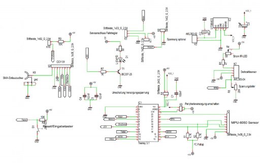
thank you for replying and sorry for the delay response. and so to your answers is, because the circuit is already been determined. meaning that i have a teensy that already connected to cc1101. below is the circuit diagramm that i talked about. thank you. circuit diagramm.jpg
 
(im using the command of Serial.vailable and Serial.read )is always a -1. Just for starting the motor, i might just use the value of -1. But i cant have any other command as it only have "-1" value regardless of what ever i send on the transmitter.

I can't really tell what your application is do you have two teensy ? one hooked to a computer? and the wireless and on to the motor and a wireless?

The keyword 'Serial' or 'Serial1' refers to the USB serial port or Uart1 on the teensy. your cc1101 seems to be connected to MOSI/MISO using a lib not included in the post so it's not possible to review and determine what might be going on in there.

in my experience Serial.available() returns -1 when nothing is available.

Can you explain the bigger picture of how you are trying to set this up?

i have two teensy. both are connected to the cc1101 as picture above. one connected to motor, the other connected to pc. so the task is to give a command from the teensy (connected to pc) to the other teensy (connected to motor) to start the motor remotely/wirelessly. i tried using virtual wire, but it doesnt seem to be working as the pinning that i have is already set.
 
Sorry, meant code. You need to treat it like an SPI device not a serial device.

edit. From a quick search of Arduino and CC1101 there appears to be a library for the CC1101.
 
Ok, now we can see you're using SPI, and you've connected to pins 11, 12 and 14.

You're going to need SPI.setSCK(14) near the beginning of your program. The default is pin 13, so this must be called before you attempt to use SPI.

I did not see any links to the ELECHOUSE_CC1101.h library or other software you're using which isn't part or Arduino or Teensyduino. If this library offers options to use SPI, I2C or serial, obviously you need to use SPI. I have no idea if this library uses SPI or something else. If you post more messages, perhaps give us links to the exact libraries you're using? Missing info makes helping you much harder.


(perhaps you can now understand why we have the "Forum Rule".... this thread now has 11 messages, mostly people trying to help you, but all their effort is spent guessing what you've done. If you had posted the schematic, all code and all the libraries in your first message, we could have helped much better, much sooner)
 
Last edited:
View attachment I2Cdev.h,
View attachment I2Cdev.cpp,
View attachment helper_3dmath..h,
View attachment ELECHOUSE_CC1101.h,
View attachment ELECHOUSE_CC1101.cpp,
View attachment bldc_control.h,
View attachment bldc_control.cpp,
View attachment MPU6050.cpp

firstly i would like to apologive to each that are trying to help me but couldnt because of the lack of information that i should be giving in the first place. And so these are all the libraries and header that im using. Again, sorry and thank you!
 

Attachments

  • ELECHOUSE_CC1101.cpp
    11.3 KB · Views: 126
  • ELECHOUSE_CC1101.h
    6.5 KB · Views: 104
Unless you're using the very latest 1.29beta3, you need to edit this code to use SPI.setSCK *before* SPI.begin

Code:
void ELECHOUSE_CC1101::SpiInit(void)
{
  // Pin initialisieren
  pinMode(ChipSelect_Pin, OUTPUT);

    //SPI initialisieren
  SPI.begin();
  // Clock-Signal auf Pin 14 mappen
  SPI.setSCK(14);


}
 
Sorry, meant code. You need to treat it like an SPI device not a serial device.

edit. From a quick search of Arduino and CC1101 there appears to be a library for the CC1101.

this is my elechouse_cc1101.cpp
PHP:
#include "ELECHOUSE_CC1101.h"
#include <Arduino.h>
#include <SPI.h>

/****************************************************************/
#define 	WRITE_BURST     	0x40						//write burst
#define 	READ_SINGLE     	0x80						//read single
#define 	READ_BURST      	0xC0						//read burst
#define 	BYTES_IN_RXFIFO     0x7F  						//byte number in RXfifo

#define         ChipSelect_Pin 6
#define         GDNull_Pin 17
/****************************************************************/
byte PaTabel[8] = {0x60 ,0x60 ,0x60 ,0x60 ,0x60 ,0x60 ,0x60 ,0x60};

/****************************************************************
*FUNCTION NAME:SpiInit
*FUNCTION     :spi communication initialization
*INPUT        :none
*OUTPUT       :none
****************************************************************/
void ELECHOUSE_CC1101::SpiInit(void)
{
  // Pin initialisieren
  pinMode(ChipSelect_Pin, OUTPUT);
  
 // Clock-Signal auf Pin 14 mappen
  SPI.setSCK(14);    //SPI initialisieren
  
  SPI.begin();


}
/****************************************************************
*FUNCTION NAME:SpiTransfer
*FUNCTION     :spi transfer
*INPUT        :value: data to send
*OUTPUT       :data to receive
****************************************************************/
byte ELECHOUSE_CC1101::SpiTransfer(byte value)
{
  //SPI.transfer(value);
  //return SPI.transfer(0);
  

  SPDR = value;
  while (!(SPSR & (1<<SPIF))) ;
  return SPDR;

}

/****************************************************************
*FUNCTION NAME: GDO_Set()
*FUNCTION     : set GDO0,GDO2 pin
*INPUT        : none
*OUTPUT       : none
****************************************************************/
void ELECHOUSE_CC1101::GDO_Set (void)
{
	 pinMode(GDNull_Pin, INPUT);
	
}

/****************************************************************
*FUNCTION NAME:Reset
*FUNCTION     :CC1101 reset //details refer datasheet of CC1101/CC1100//
*INPUT        :none
*OUTPUT       :none
****************************************************************/
void ELECHOUSE_CC1101::Reset (void)
{
	digitalWrite(ChipSelect_Pin, LOW);
	delay(1);
	digitalWrite(ChipSelect_Pin, HIGH);
	delay(1);
	digitalWrite(ChipSelect_Pin, LOW);
	delay(1);
	SpiTransfer(CC1101_SRES);
	delay(1);
	digitalWrite(ChipSelect_Pin, HIGH);
}

/****************************************************************
*FUNCTION NAME:Init
*FUNCTION     :CC1101 initialization
*INPUT        :none
*OUTPUT       :none
****************************************************************/
void ELECHOUSE_CC1101::Init(void)
{
	SpiInit();										//spi initialization
	GDO_Set();										//GDO set
	digitalWrite(ChipSelect_Pin, HIGH);
	Reset();										//CC1101 reset
	RegConfigSettings();							//CC1101 register config
	SpiWriteBurstReg(CC1101_PATABLE,PaTabel,8);		//CC1101 PATABLE config
}


/****************************************************************
*FUNCTION NAME:SpiWriteReg
*FUNCTION     :CC1101 write data to register
*INPUT        :addr: register address; value: register value
*OUTPUT       :none
****************************************************************/
void ELECHOUSE_CC1101::SpiWriteReg(byte addr, byte value)
{
        SPI.beginTransaction(SPISettings(4000000, MSBFIRST, SPI_MODE0));
	digitalWrite(ChipSelect_Pin, LOW);
	SpiTransfer(addr);
	SpiTransfer(value);
	digitalWrite(ChipSelect_Pin, HIGH);
        SPI.endTransaction();
}

/****************************************************************
*FUNCTION NAME:SpiWriteBurstReg
*FUNCTION     :CC1101 write burst data to register
*INPUT        :addr: register address; buffer:register value array; num:number to write
*OUTPUT       :none
****************************************************************/
void ELECHOUSE_CC1101::SpiWriteBurstReg(byte addr, byte *buffer, byte num)
{
	byte i, temp;

	temp = addr | WRITE_BURST;
    SPI.beginTransaction(SPISettings(4000000, MSBFIRST, SPI_MODE0));
    digitalWrite(ChipSelect_Pin, LOW);
    delay(1);
    SpiTransfer(temp);
    for (i = 0; i < num; i++)
 	{
        SpiTransfer(buffer[i]);
    }
    digitalWrite(ChipSelect_Pin, HIGH);
      SPI.endTransaction();
}

/****************************************************************
*FUNCTION NAME:SpiStrobe
*FUNCTION     :CC1101 Strobe
*INPUT        :strobe: command; //refer define in CC1101.h//
*OUTPUT       :none
****************************************************************/
void ELECHOUSE_CC1101::SpiStrobe(byte strobe)
{
	SPI.beginTransaction(SPISettings(4000000, MSBFIRST, SPI_MODE0));
        digitalWrite(ChipSelect_Pin, LOW);
	delay(1);
	SpiTransfer(strobe);
	digitalWrite(ChipSelect_Pin, HIGH);
        SPI.endTransaction();
}

/****************************************************************
*FUNCTION NAME:SpiReadReg
*FUNCTION     :CC1101 read data from register
*INPUT        :addr: register address
*OUTPUT       :register value
****************************************************************/
byte ELECHOUSE_CC1101::SpiReadReg(byte addr) 
{
	byte temp, value;

    temp = addr|READ_SINGLE;
	SPI.beginTransaction(SPISettings(4000000, MSBFIRST, SPI_MODE0));
        digitalWrite(ChipSelect_Pin, LOW);
	delay(1);
	SpiTransfer(temp);
	value=SpiTransfer(0);
	digitalWrite(ChipSelect_Pin, HIGH);
        SPI.endTransaction();

	return value;
}

/****************************************************************
*FUNCTION NAME:SpiReadBurstReg
*FUNCTION     :CC1101 read burst data from register
*INPUT        :addr: register address; buffer:array to store register value; num: number to read
*OUTPUT       :none
****************************************************************/
void ELECHOUSE_CC1101::SpiReadBurstReg(byte addr, byte *buffer, byte num)
{
	byte i,temp;

	temp = addr | READ_BURST;
	SPI.beginTransaction(SPISettings(4000000, MSBFIRST, SPI_MODE0));
        digitalWrite(ChipSelect_Pin, LOW);
	delay(1);
	SpiTransfer(temp);
	for(i=0;i<num;i++)
	{
		buffer[i]=SpiTransfer(0);
	}
	digitalWrite(ChipSelect_Pin, HIGH);
        SPI.endTransaction();
}

/****************************************************************
*FUNCTION NAME:SpiReadStatus
*FUNCTION     :CC1101 read status register
*INPUT        :addr: register address
*OUTPUT       :status value
****************************************************************/
byte ELECHOUSE_CC1101::SpiReadStatus(byte addr) 
{
	byte value,temp;

	temp = addr | READ_BURST;
	SPI.beginTransaction(SPISettings(4000000, MSBFIRST, SPI_MODE0));
        digitalWrite(ChipSelect_Pin, LOW);
	delay(1);
	SpiTransfer(temp);
	value=SpiTransfer(0);
	digitalWrite(ChipSelect_Pin, HIGH);
        SPI.endTransaction();

	return value;
}

/****************************************************************
*FUNCTION NAME:RegConfigSettings
*FUNCTION     :CC1101 register config //details refer datasheet of CC1101/CC1100//
*INPUT        :none
*OUTPUT       :none
****************************************************************/
void ELECHOUSE_CC1101::RegConfigSettings(void) 
{
  
  
    SpiWriteReg(CC1101_FSCTRL1,  0x08);
     SpiWriteReg(CC1101_FREQ2,    0x10);
    SpiWriteReg(CC1101_FREQ1,    0xA7);
    SpiWriteReg(CC1101_FREQ0,    0x62);
    SpiWriteReg(CC1101_MDMCFG4,  0x5B);
   SpiWriteReg(CC1101_MDMCFG3,  0xF8);
   SpiWriteReg(CC1101_MDMCFG2,  0x03);
  SpiWriteReg(CC1101_DEVIATN,  0x47);
  SpiWriteReg(CC1101_FOCCFG,   0x1D);
  SpiWriteReg(CC1101_FSCAL3,   0xEA);
      SpiWriteReg(CC1101_FSCAL0,   0x11);
      
  
    SpiWriteReg(CC1101_FSCTRL0,  0x00);
    SpiWriteReg(CC1101_MDMCFG1,  0x22);
    SpiWriteReg(CC1101_MDMCFG0,  0xF8);
    SpiWriteReg(CC1101_CHANNR,   0x00);
   
    SpiWriteReg(CC1101_FREND1,   0xB6);
    SpiWriteReg(CC1101_FREND0,   0x10);
    SpiWriteReg(CC1101_MCSM0 ,   0x18);
    
    SpiWriteReg(CC1101_BSCFG,    0x1C);
    SpiWriteReg(CC1101_AGCCTRL2, 0xC7);
	SpiWriteReg(CC1101_AGCCTRL1, 0x00);
    SpiWriteReg(CC1101_AGCCTRL0, 0xB2);
    
	SpiWriteReg(CC1101_FSCAL2,   0x2A);
	SpiWriteReg(CC1101_FSCAL1,   0x00);

    SpiWriteReg(CC1101_FSTEST,   0x59);
    SpiWriteReg(CC1101_TEST2,    0x81);
    SpiWriteReg(CC1101_TEST1,    0x35);
    SpiWriteReg(CC1101_TEST0,    0x09);
    SpiWriteReg(CC1101_IOCFG2,   0x0B); 	//serial clock.synchronous to the data in synchronous serial mode
    SpiWriteReg(CC1101_IOCFG0,   0x06);  	//asserts when sync word has been sent/received, and de-asserts at the end of the packet 
    SpiWriteReg(CC1101_PKTCTRL1, 0x04);		//two status bytes will be appended to the payload of the packet,including RSSI LQI and CRC OK
											//No address check
    SpiWriteReg(CC1101_PKTCTRL0, 0x05);		//whitening off;CRC Enable��variable length packets, packet length configured by the first byte after sync word
    SpiWriteReg(CC1101_ADDR,     0x00);		//address used for packet filtration.
    SpiWriteReg(CC1101_PKTLEN,   0x3D); 	//61 bytes max length
    
    //Abweichungen
    /*
    SpiWriteReg(CC1101_FSCTRL1,  0x06);
    SpiWriteReg(0x03,0x47);
    SpiWriteReg(CC1101_FREQ2,    0x21);
    SpiWriteReg(CC1101_FREQ1,    0x62);
    SpiWriteReg(CC1101_FREQ0,    0x76);
    SpiWriteReg(CC1101_MDMCFG4,  0xF5);
    SpiWriteReg(CC1101_MDMCFG3,  0x83);
    SpiWriteReg(CC1101_MDMCFG2,  0x13);
    SpiWriteReg(CC1101_DEVIATN,  0x15);
    SpiWriteReg(CC1101_FOCCFG,   0x16);
    SpiWriteReg(0x20,   0xFB);
    SpiWriteReg(CC1101_FSCAL3,   0xE9);
    SpiWriteReg(CC1101_FSCAL0,   0x1F);
     SpiWriteReg(CC1101_TEST2,    0x81);*/
}

/****************************************************************
*FUNCTION NAME:SendData
*FUNCTION     :use CC1101 send data
*INPUT        :txBuffer: data array to send; size: number of data to send, no more than 61
*OUTPUT       :none
****************************************************************/
void ELECHOUSE_CC1101::SendData(byte *txBuffer,byte size)
{
	SpiWriteReg(CC1101_TXFIFO,size);
	SpiWriteBurstReg(CC1101_TXFIFO,txBuffer,size);			//write data to send
	SpiStrobe(CC1101_STX);									//start send	
//  Knop 14.05.Hier hängt das Programm
      while (!digitalRead(GDNull_Pin));								// Wait for GDO0 to be set -> sync transmitted  
      while (digitalRead(GDNull_Pin));								// Wait for GDO0 to be cleared -> end of packet
	SpiStrobe(CC1101_SFTX);									//flush TXfifo
}

/****************************************************************
*FUNCTION NAME:SetReceive
*FUNCTION     :set CC1101 to receive state
*INPUT        :none
*OUTPUT       :none
****************************************************************/
void ELECHOUSE_CC1101::SetReceive(void)
{
	SpiStrobe(CC1101_SRX);
}

/****************************************************************
*FUNCTION NAME:CheckReceiveFlag
*FUNCTION     :check receive data or not
*INPUT        :none
*OUTPUT       :flag: 0 no data; 1 receive data 
****************************************************************/
byte ELECHOUSE_CC1101::CheckReceiveFlag(void)
{
	if(digitalRead(GDNull_Pin))			//receive data
	{
		while (digitalRead(GDNull_Pin));
		return 1;
	}
	else							// no data
	{
		return 0;
	}
}


/****************************************************************
*FUNCTION NAME:ReceiveData
*FUNCTION     :read data received from RXfifo
*INPUT        :rxBuffer: buffer to store data
*OUTPUT       :size of data received
****************************************************************/
byte ELECHOUSE_CC1101::ReceiveData(byte *rxBuffer)
{
	byte size;
	byte status[2];

	if(SpiReadStatus(CC1101_RXBYTES) & BYTES_IN_RXFIFO)
	{
		size=SpiReadReg(CC1101_RXFIFO);
		SpiReadBurstReg(CC1101_RXFIFO,rxBuffer,size);
		SpiReadBurstReg(CC1101_RXFIFO,status,2);
		SpiStrobe(CC1101_SFRX);
		return size;
	}
	else
	{
		SpiStrobe(CC1101_SFRX);
		return 0;
	}
	
}

ELECHOUSE_CC1101 ELECHOUSE_cc1101;

is it not treated as an spi devices?
 
Status
Not open for further replies.
Back
Top