You are using an out of date browser. It may not display this or other websites correctly.
You should upgrade or use an alternative browser.
You should upgrade or use an alternative browser.
Using SparkFun's RFM69HCW and Bi-Directional Logic Level Converter with Teensy 3.2
- Thread starter bugeye60
- Start date
- Status
- Not open for further replies.
davidthings
Member
Code that seems to work - T3.2 & Adafruit RFM69HW
Hi BugEye,
I have been working on a similar setup and thanks to TinMan, got it working yesterday.
I started by getting two Moteinos talking to each other (using the RadioHead library), then seeing if I could get the Teensy-based version to work with them.
I grabbed the latest RadioHead (Master, HEAD) from Github (where someone kindly mirrors the main RadioHead site)
https://github.com/Yveaux/RadioHead
The Adafruit breakout board is similar to the Sparkfun verison.
https://learn.adafruit.com/adafruit...m95-rfm98-lora-packet-padio-breakouts/pinouts
vs
https://learn.sparkfun.com/tutorials/rfm69hcw-hookup-guide
Contra Paul (a practice I try to avoid) there is a level translator on the Adafruit board, but I'm running the board at 3.3V so it's just a complex delay!
I bashed my head bloody on it, reading from all the sources, printf'ing everywhere. Finally TinMan helped me see I was not doing the right thing for the R (RST) pin. The Adafruit doc was wrong and had it active low, so I was holding the chip in RESET and nothing was working. The symptom was that it just locked up in init().
I corrected my reset code to the following:
Clearly here I'm driving the RESET back to LOW again.
I tried the technique you're using on my code
And it definitely locks up. It does not work. Remember I'm going through a level shifter which probably doesn't like being floated too much, but could this be a clue? Maybe try driving the pin low again?
I have only one piece of code to share the rf_client - I'm running the server on the Moteino unmodified.
Hi BugEye,
I have been working on a similar setup and thanks to TinMan, got it working yesterday.
I started by getting two Moteinos talking to each other (using the RadioHead library), then seeing if I could get the Teensy-based version to work with them.
I grabbed the latest RadioHead (Master, HEAD) from Github (where someone kindly mirrors the main RadioHead site)
https://github.com/Yveaux/RadioHead
The Adafruit breakout board is similar to the Sparkfun verison.
https://learn.adafruit.com/adafruit...m95-rfm98-lora-packet-padio-breakouts/pinouts
vs
https://learn.sparkfun.com/tutorials/rfm69hcw-hookup-guide
Contra Paul (a practice I try to avoid) there is a level translator on the Adafruit board, but I'm running the board at 3.3V so it's just a complex delay!
I bashed my head bloody on it, reading from all the sources, printf'ing everywhere. Finally TinMan helped me see I was not doing the right thing for the R (RST) pin. The Adafruit doc was wrong and had it active low, so I was holding the chip in RESET and nothing was working. The symptom was that it just locked up in init().
I corrected my reset code to the following:
Code:
  pinMode( RFM69_RST, OUTPUT );
  digitalWrite( RFM69_RST, HIGH); // RESET
  delay( 100 );
  digitalWrite( RFM69_RST, LOW); // ~RESET
  delay( 100 );
Clearly here I'm driving the RESET back to LOW again.
I tried the technique you're using on my code
Code:
  pinMode( RFM69_RST, OUTPUT );
  digitalWrite( RFM69_RST, HIGH); // RESET
  delay( 100 );
  pinMode( RFM69_RST, INPUT );
  delay( 100 );
And it definitely locks up. It does not work. Remember I'm going through a level shifter which probably doesn't like being floated too much, but could this be a clue? Maybe try driving the pin low again?
I have only one piece of code to share the rf_client - I'm running the server on the Moteino unmodified.
Code:
// rf69_client.pde
// -*- mode: C++ -*-

#include <SPI.h>

#include <RH_RF69.h>

#define RFM69_RST 5
#define RFM69_EN  6
#define RFM69_SS  8
#define RFM69_IRQ 7

#define TFT_CS    10

// Singleton instance of the radio driver
// Want ( SS pin, IRQ pin )

//digitalWrite( RFM69_EN, HIGH); // Enable
RH_RF69 rf69(RFM69_SS, RFM69_IRQ );

void setup()
{
  pinMode( RFM69_RST, OUTPUT );
  digitalWrite( RFM69_RST, HIGH); // RESET
  delay( 100 );
  // pinMode( RFM69_RST, INPUT ); // Doesn't work
  digitalWrite( RFM69_RST, LOW); // Works
  delay( 100 );

  pinMode( RFM69_EN, OUTPUT );
  digitalWrite( RFM69_EN, HIGH); // Enable

  pinMode( TFT_CS, OUTPUT );
  digitalWrite( TFT_CS, HIGH ); // TFT Chip select

  Serial.begin(115200);
  delay( 1000 );
  Serial.printf( "Start\n" );
  delay( 1000 );

  if (!rf69.init())
    Serial.println("init failed");

  Serial.printf( "Init() Successful\n" ); delay( 1000 );

  // Defaults after init are 434.0MHz, modulation GFSK_Rb250Fd250, +13dbM
  // No encryption

  if (!rf69.setFrequency(915.0))
    Serial.println("setFrequency failed");

  // If you are using a high power RF69, you *must* set a Tx power in the
  // range 14 to 20 like this:
  rf69.setTxPower(20);

  // The encryption key has to be the same as the one in the server
  uint8_t key[] = { 0x01, 0x02, 0x03, 0x04, 0x05, 0x06, 0x07, 0x08,
                    0x01, 0x02, 0x03, 0x04, 0x05, 0x06, 0x07, 0x08};
  rf69.setEncryptionKey(key);

  //rf69.setModemConfig( RH_RF69::GFSK_Rb55555Fd50 );

  Serial.println( "Init-ed" );
}

void loop()
{
  Serial.print("Sending to rf69_server ");
  Serial.println( millis() / 1000 );
  // Send a message to rf69_server
  uint8_t data[] = "Hello Teensy World!";
  rf69.send(data, sizeof(data));
  Serial.println("Waiting for sent");
  rf69.waitPacketSent();
  Serial.println("Sent.  Waiting for reply");
  // Now wait for a reply
  uint8_t buf[RH_RF69_MAX_MESSAGE_LEN];
  uint8_t len = sizeof(buf);

  if (rf69.waitAvailableTimeout(500))
  {
    // Should be a reply message for us now
    if (rf69.recv(buf, &len))
    {
      Serial.print("got reply: ");
      Serial.println((char*)buf);
    }
    else
    {
      Serial.println("recv failed");
    }
  }
  else
  {
    Serial.println("No reply, is rf69_server running?");
  }
  delay(1000);
}davidthings
Member
One further observation: when it's working, the LED on D13 blinks. When it doesn't, it's solid on. (Because it's hung busy waiting for the MODEREADY flag to be asserted, which it isn't because the unit is in RESET!)
The fact that setting the reset pin LOW is required could indeed have something to do with the level shifter, I for sure know it's not necessary when the reset pin is directly connected from a digital pin on the Teensy to the RFM module.
@Bugeye60, yes, perhaps it's a good idea to give another library a shot... hopefully that works out of the box
@Bugeye60, yes, perhaps it's a good idea to give another library a shot... hopefully that works out of the box
davidthings
Member
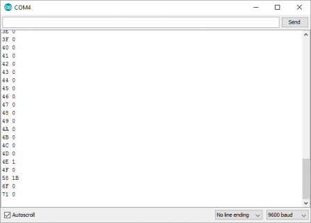
Another thing that someone helpful suggested was to dump the registers. If you can get good register values, for example an 0x24 from Register 0x10, you can be confident that your main SPI connection is good - CLK, MOSI, MISO, CS. You can't get register values if any of these is unhappy. I did it in bool RH_RF69::init() right before the setIdleMode() call - because in my case that was where execution was hanging.
Last edited:
davidthings
Member
In the init function, before the setModeIdle() (approximately line 150) just call:
At startup you'll get a column of numbers.
I get:
Code:
printRegisters();At startup you'll get a column of numbers.
I get:
Code:
0 0
1 4
2 0
3 1A
4 B
...I conducted four different trials today and still am not receiving a message. My conclusion thus far is that the printRegisters is operating as intended and that both resets from iwanders and davidthings have the same result.
Here's a description of my four attempts. I've also attached associated code (but was unable to attach RH_RF69.h).
First Attempt:
The output from this attempt is shown below:
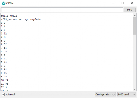
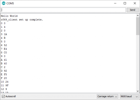
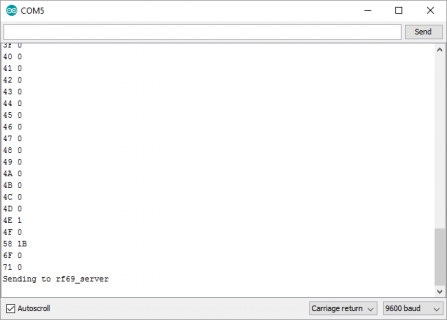
Although not shown, the server did not receive or acknowledge the message from the client.
Second Attempt:
Result:
Third Attempt:
Result:
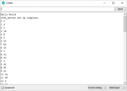
Fourth Attempt:
Result:
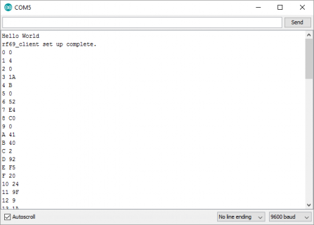
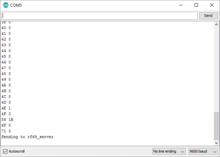
Here's a description of my four attempts. I've also attached associated code (but was unable to attach RH_RF69.h).
First Attempt:
- Downloaded the most recent RadioHead library files from www.airspace.com/mikem/aduino/RadioHead
- Removed the RadioHead library files from c:\Program Files (x86)\Arduino\hardware\teensy\avr\libraries\RadioHead
- Installed the new RadioHead library files to the same same location.
- Modified RH_RF69.cpp to add printRegisters(); just above the setModeIdle(); around line 150
- Modified rf69server and rf69client in the Examples
- Added hardware resets per davidthings, first thing in setup()
Code:
// Perform a hardware reset per davidthings.  The reset pin on the RFM69HCW is set to Teensy 3.2 digital pin 6
pinMode(6, OUTPUT);
digitalWrite(6, HIGH);  //RESET
delay( 100);
digitalWrite(6, LOW); // ~RESET
delay(100);
// end of reset;- Directly after Serial.begin(9600); added
Code:
// Previously added delay may be unnecessary now:
 while (!Serial && (millis() <= 8000));
  Serial.println("Hello World");
  Serial.println("rf69_server set up complete.");
// End of my addition- Modified if (!rf69.setFrequency(433.0)) to use 915.0 instead of 433.0
- Uncommented line rf69.setTxPower(14);
- (Server and client mods are the same except the print statements regarding set up complete.
The output from this attempt is shown below:


Although not shown, the server did not receive or acknowledge the message from the client.
Second Attempt:
- Commented line RH_RF69 rf69;
- Uncommented line RH_RF69 rf69(15, 16); because I wasn't sure if this referred to any Teensy-compatible breakout board or PJRC's proprietary one.
Result:
- Same output on server, then a solid LED
- Significantly different output on the client. No register data was printed and I received an 'init failed' message.
Third Attempt:
- Kept the same RH_RF69 rf(15, 16);
- Reverted back to iwanders reset on both server and client
Code:
  pinMode(6, OUTPUT);
  digitalWrite(6, HIGH);  //RESET
  delayMicroseconds(150);
  pinMode(6, INPUT); // ~RESET
  delay(100);
  // end of reset;
Result:
- Same as second attempt.
Fourth Attempt:
- Revert back to the original RH_RF69 rf69;
- Keep the iwanders reset from the third attempt
Result:
- Same as attempt #1
- Solid LED is gone


Attachments
By default the constructor is called with interruptPin=2, just to be certain, DIO0 of the RFM radio module was wired to Pin 2 on the Teensy? That pin is used to read whether the radio has finished transmission or has received anything.Uncommented line RH_RF69 rf69(15, 16); because I wasn't sure if this referred to any Teensy-compatible breakout board or PJRC's proprietary one.
If that pin is also correctly connected, I'm at a loss... :/
defragster
Senior Member+
- Downloaded the most recent RadioHead library files from www.airspace.com/mikem/aduino/RadioHead
- Removed the RadioHead library files from c:\Program Files (x86)\Arduino\hardware\teensy\avr\libraries\RadioHead
- ...
This thread today by @davidthings may save you trouble starting with latest Radiohead: RadioHead-with-SPI-transactions-success-with-RFM69HCW-and-ILI9341-based-TFT
Question: Anyone seen how similar are the software interfaces are between RFM69 and RFM95? I understand the radio usage isn't compatible - but when I get the PCB's and think about trying I'm hoping the work here will apply to my hardware.
BTW- the p#35 link above didn't work for me - but the one on thread here above did - and there I see a unique RH_RF95.cpp as well as the RH_RF69.cpp support. And we learned the pinout is the same.
Last edited:
defragster
Senior Member+
@iwanders - I ordered your board from https://pcbs.io/search (that link goes to the shared boards page)
I should be getting a set in a week or two. Cost was $1.25+$1.40 for what will be 4 (perhaps 6) units of the two parts. With your permission I could mark the board for display on the SHARED page linked above and anyone could order from there - as it is done on OSH. If you ever order from there you could share it or other boards. There is a percentage of board cost accumulated as a reward each time a shared board is ordered.
For instance FrankB shared this: https://PCBs.io/share/46718
Could wait to be sure it works - the other boards I've gotten from there seem to be good.
My connections are:
RFM69HCW > Teensy 3.2
O (MISO) > 12 (DIN)
I (MOSI) > 11 (DOUT)
C (SCK) > 13 (SCK)
S (NSS) > 10 (CS)
0 (DIO0) > 2
G (GND) > GND (next to digital pin 0)
3.3V > 3.3V (pin next to AGND and digital pin 23)
A (ANT) > 78 mm wire antenna
Radio pins 1-5 remain unused.
I see there is an antenna ground pin also. I am not using it. Do I need to ground my wire antenna also??
What do the 15 and 16 refer to in the line RH_RF69 rf69(15,16)?
davidthings
Member
The RH_RF69 function rf69( ) takes two parameters, the CS pin and the IRQ pin. When you init with 15 and 16, you're telling the code CS is pin 15, IRQ is pin 16.
davidthings
Member
Like iwanders, I'm drawn to looking at the IRQ line. Obviously all the other lines are OK, or else you wouldn't be seeing reasonable register values. (Need clk, data out (register address) data in (register data) and cs (chip listening))
Is it possible you have the IRQ connected to the wrong pin on the Teensy - I've been caught out by the existence of a pin 0! Pin 2 is the forth one down!
If I were you, I think I'd buy a couple (or three) Moteino's and use them to check the teensy. Why?
Because you're probably sick to death of seeing no result at all. This way you can start with two talking Moteinos and see something really working!
Because there is no wiring. No connections to get wrong.
Because they're tested.
Because with working Moteinos you can then see if the Teensy-based hardware is not transmitting or not receiving (or both).
Working with wireless can be ridiculously frustrating without known good starting points.
That's what I would do - in fact that's what I did... Although I had the Moteinos lying around.
Confirmed - I am using digital pin 2, fourth one from the end: 1st pin = GND, 2nd pin = digital pin 0, 3rd pin = digital pin 1, 4th pin = digital pin 2.
@davidthings, any recommendation for which Moteino to purchase? I understand your logic - reduce the unknowns by using something that works first and gradually introduce my radio.
@davidthings, any recommendation for which Moteino to purchase? I understand your logic - reduce the unknowns by using something that works first and gradually introduce my radio.
davidthings
Member
I personally like the Moteino USB
- easy to power with USB battery
- always able to reprogram without finding other boards
- easy to power with USB battery
- always able to reprogram without finding other boards
tinman13kup
Member
WELL HOT DIGGI... I got my pair of TLCs working....kind of. I'm scratching my head at the moment, but I have success. It turns out my issue was the wrong IRQ no. It (I) was using 0 instead of 10. My fault for being a newbie.
Anyhow, here is my mismash of code that got me going-- Be easy on me
It needs a little tweaking, and it is a mix of Sparkfun, Adafruit, and my own lines derived from the -h files.
My issue is that I found my error, fixed it, and reloaded both T-LCs off separate ide windows. I changed the sender/receiver nodes accordingly and what do I get????
One node one node that will receive and the other transmit (of course), but it will not send from the second node back to the first. ????????
I don't know if the IRQ needs to be changed for the other T's, but maybe this will help.
Any pointers on what I have are good too. I'm still too new to this to have developed any habits, good or bad yet.
Anyhow, here is my mismash of code that got me going-- Be easy on me
Code:
#include "RFM69.h"
#include <SPI.h>

#define networkID   1 //same for all nodes
#define SENDERID   2 //This node id
#define TARGETID   1 // to receiving node

#define freqBand  RF69_915MHZ
#define ENCRYPT false //set to true for encryption
#define ENCRYPTKEY  "sampleEncryptKey" //all nodes must have the same
#define ACKrequested  false  //set to true for acknowledgement
#define _isRFM69HW  // comment out for RFM69W
#define LED 15
#define SERIAL_Baud 115200

//for Teensy-LC
#define RF69_RST  9
#define RF69_CS  10
#define RF69_IRQ_pin  2
#define RF69_IRQ_NUM  10
RFM69 radio;

void setup()
{
  // put your setup code here, to run once:
while (!Serial);
Serial.begin(9600);
Serial.println("RFM69HCW ready");
//Reset the RFM module
pinMode(RF69_RST,OUTPUT);
digitalWrite(RF69_RST,HIGH);
delay(100);
digitalWrite(RF69_RST,LOW);
delay(100);

radio.initialize(freqBand, SENDERID, networkID);
radio.setHighPower();
radio.setPowerLevel(31); //power level ranges from 0 (5dBm)

/*  if (ENCRYPT)
radio.encrypt(ENCRYPTKEY);*/

}

void loop()
{
  static char sendbuffer[62];
  static int sendlength = 0;
  if (Serial.available() > 0)
  {
    char input = Serial.read();
    if (input != '\r')
    {
      sendbuffer[sendlength] = input;
      sendlength++;
    }
    if ((input =='\r') || (sendlength == 61))
    {
      Serial.print("sending to node");
      Serial.print(SENDERID,DEC);
      for (byte i=0; i < sendlength; i++)
         Serial.print(sendbuffer[i]);
         Serial.println("]");

      if (ACKrequested)
      {
        if (radio.sendWithRetry(TARGETID, sendbuffer, sendlength))
        Serial.println("ACK received");
        else
        Serial.println("No ACK");
      }
      else
      {
        radio.send(TARGETID, sendbuffer, sendlength);
      }
      sendlength = 0;
      digitalWrite(LED,HIGH);
      delay(20);
      digitalWrite(LED,LOW);
      delay(20);


    }
  }
if (radio.receiveDone())
{
  Serial.print("received from node");
  Serial.print(SENDERID, DEC);
  Serial.print("message [");

  for (byte i= 0; i < radio.DATALEN; i++)
  Serial.print((char)radio.DATA[i]);
  Serial.print("],RSSI");
  Serial.println(radio.RSSI);

  if (radio.ACKRequested())
  {radio.sendACK();
  Serial.println("ACK sent");
  }
  digitalWrite(LED,HIGH);
      delay(20);
      digitalWrite(LED,LOW);
      delay(20);
}
}
It needs a little tweaking, and it is a mix of Sparkfun, Adafruit, and my own lines derived from the -h files.
My issue is that I found my error, fixed it, and reloaded both T-LCs off separate ide windows. I changed the sender/receiver nodes accordingly and what do I get????
One node one node that will receive and the other transmit (of course), but it will not send from the second node back to the first. ????????
I don't know if the IRQ needs to be changed for the other T's, but maybe this will help.
Any pointers on what I have are good too. I'm still too new to this to have developed any habits, good or bad yet.
tinman13kup
Member
As for my onboard led, I just noticed that the LC that receives (no TX) has the led lit, but the other LC (TX, no RX) does not. Since I'm using that pin as SCK, which one is suspect?
defragster
Senior Member+
Good news on seeing it work.
With SCK on p13 the LED will flash when there is any transmission. No flash - then no transfer is happening. LED will normally be off when no activity.As for my onboard led, I just noticed that the LC that receives (no TX) has the led lit, but the other LC (TX, no RX) does not. Since I'm using that pin as SCK, which one is suspect?
As I read that you have multiple units connected and in the case of Teensy you can't select which one downloads? Try TYQT - You can push button from GUI or have it replace TeensyDuino and it will allow selection of the device from a given IDE instance. Very flexible and feature filled and a great Serial Monitor too that can run multiple copies for multiple devices....
- always able to reprogram without finding other boards
Last edited:
tinman13kup
Member
Good news on seeing it work.
With SCK on p13 the LED will flash when there is any transmission. No flash - then no transfer is happening. LED will normally be off when no activity.
I reloaded both LCs, changing only the send/rcv node #s and I'm back to square one. Both onboard led's come on as soon as a serial window is opened and remain on. Bummer
To ensure that you don't have to worry about separately uploading an server and a client program you might want to have both use the same sketch and depending on a digitalRead() drop either into server or client mode. Something like this (taken from my library's example):
To me, that greatly simplifies the testing as you can just upload, and the Teensy loader uploads to one, to upload to the other as well you just press the program button on that Teensy as well. So yes, you have to do two uploads, but you are always sure that both are programmed with the same code.
Other than that, I'm sort of disappointed that it's not yet working for Bugeye, despite our combined efforts to help out...
Code:
if (digitalRead(SENDER_DETECT_PIN) == LOW){
        Serial.println("Going Receiver!");
        receiver(); // this function never returns and contains an infinite loop.
    } else {
        Serial.println("Going sender!");
        sender(); // this function never returns and contains an infinite loop.
}Other than that, I'm sort of disappointed that it's not yet working for Bugeye, despite our combined efforts to help out...
defragster
Senior Member+
My copies of the iwanders two part mount boards showed up today. $2.65 and I got 5 copies of each.
BUMMER <edit> - it's confirmed the FAB missed holes on many boards all over a whole panel.
PROBLEM:: I just noticed the pads are not drilled through!!!!!
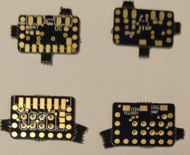
<edit> :: Looking at the images on the order the drill holes look to have been right - I sent email - for confirmation - may have just missed a processing step.
BUMMER <edit> - it's confirmed the FAB missed holes on many boards all over a whole panel.
PROBLEM:: I just noticed the pads are not drilled through!!!!!

<edit> :: Looking at the images on the order the drill holes look to have been right - I sent email - for confirmation - may have just missed a processing step.
@iwanders - I ordered your board from https://pcbs.io/search (that link goes to the shared boards page)
...
Last edited:
- Status
- Not open for further replies.

