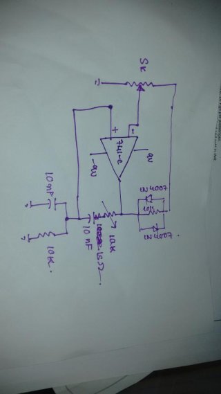
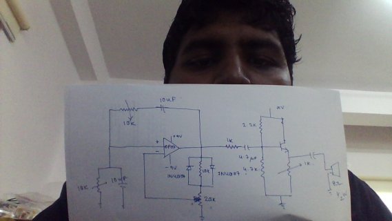
Hi, here's what I remember about wien bridge oscillators. AFAIR, the two resistors and the two capacitors in the frequency-defining part need to match, so to make the frequency tunable you need a dual potentiometer or a dual adjustable capacitor, so this might explain the distortion.
Next is the negative feedback part that sets the gain. for a stable oscillation, the feedback needs to set the gain to exactly 3, which is impossible to achieve with resistors alone as they will drift and the oscillation will either die off or grow bigger until the output is limited by the rail voltages. That's why you insert a nonlinear element, in your case the diodes, to lower the gain when a certain amplitude is reached (when the diodes start conducting). But sadly, because of the nonlinear behavior, the output will contain harmonics, which might be why you see a more triangular shape. If you want to keep the approach using diodes, switch to 1N4148 diodes and put small resistors in series with the diodes. You'll have to experiment with the values, my guess is something between 10 and 200 Ohms.
To drive anything under about 500 Ohms, you should always consider using a dedicated amp, so an lm386 will be a good idea in your case.
Another approach that will lead to very low harmonic distortion (-80dB or better can be done!) is the use of a small tungsten light bulb as a resistor in the feedback path. The bulb would go where your 5k pot is now. tungsten is a temperature-dependent resistor. Current flowing through the resistor will warm up the tungsten filament, raising its resistance, lowering the gain. This will lead to very low distortion, because the thermal capacity of the bulb stabilizes the amplitude over the course of many oscillations (large thermal time constant). The drawback is that the feedback path needs to be low resistance to allow for sufficient current in the bulb, so you could use one of those op amp buffers (BUF634, LT1010, OPA633, ...) or a discrete output stage. You'll also need large output swing, so for high frequencies the op amp may reach it's slew rate limit, especially the old 741 which has a slew rate of less than 1V/us.
 . I wanted to change the frequency by using a pot . But it starts to distort after 12 Khz. Also when i am reducing both the capacitors to 1 nF I find the waveform to be triangular more than sinusoidal. Also if I want to drive 0.5 w 8 ohm ospeaker should i use an op amp or an lm386 ?
 . I wanted to change the frequency by using a pot . But it starts to distort after 12 Khz. Also when i am reducing both the capacitors to 1 nF I find the waveform to be triangular more than sinusoidal. Also if I want to drive 0.5 w 8 ohm ospeaker should i use an op amp or an lm386 ?

