Realtime Beat Detection and Audio Analysis + DMX Master Demonstration

Status
Not open for further replies.

neltnerb

Well-known member
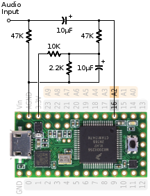
I made this recently, based on many years of experience figuring out good ways to produce intuitive lighting effects based on real-time audio analysis. I am hopeful that others may find this useful as either a starting point or directly in your projects!

I actually avoid using FFTs for these sorts of things since I find the effects of binning to be rather counter-intuitive for actual viewers. Instead I steadily rotate the hue of all the lights in the DMX universe while pulsing based on beat detection of the overall RMS audio signal. The result is generally much snappier response times and very synesthetic effects.

https://github.com/saikoLED/TeensyLED/tree/master/Examples/TeensyLED_Audio_DMX_Master

Video of the code in operation during testing, alas I didn't get a video of it at the arts festival where I set up the full installation.

https://www.youtube.com/watch?v=BOnsDaA30Ak
 
Awww that's awesome! I'm setting up a home gym / minibar in my garage and this will most definitely be implemented! I already have a run of WS2812 LEDs to play with :)

Thank you!!!
 
Awww that's awesome! I'm setting up a home gym / minibar in my garage and this will most definitely be implemented! I already have a run of WS2812 LEDs to play with :)

Thank you!!!
i'll need to fork it and adapt it to use the audio shield for input and send the 8 HSI channel outputs via each channel of an octoWS2811 (fastLED supports HSI out of the box ;) )

This will create a budget/homegeek alternative version for people like me without any DMX kit and a pile of WS2812b stuff to play with :)

I was going to buy one of those TeensyLED DMX boards and some DMX lights until i costed the whole project EEEK =| I'mtoo poor for such expenditure.

Might take a few months though - have a project to finish and another big one to start first....
 
Any chance you might release this under a MIT-like license, so it could be merged into the audio library?

Or would it be ok to just use the algorithm (on MIT terms), it reimplemented in fixed point?
 
i'll need to fork it and adapt it to use the audio shield for input and send the 8 HSI channel outputs via each channel of an octoWS2811 (fastLED supports HSI out of the box ;) )

This will create a budget/homegeek alternative version for people like me without any DMX kit and a pile of WS2812b stuff to play with :)

I was going to buy one of those TeensyLED DMX boards and some DMX lights until i costed the whole project EEEK =| I'mtoo poor for such expenditure.

Might take a few months though - have a project to finish and another big one to start first....

How did you go with this?
 
Hey Paul, sorry I seem to have totally missed the email notification that you replied. I have updated the license on the code to the MIT license and would be honored if you included something based on it in the audio library.
 
Hey Paul, sorry I seem to have totally missed the email notification that you replied. I have updated the license on the code to the MIT license and would be honored if you included something based on it in the audio library.

Bump!

I have a teensy 3.2/octows2811 adapter hooked up to a tree of lights ready to test.
I have a heap of other sequences that look a bit rubbish and suspect my implementation of beat detection would be the same.
I started doing a bit of testing with the audio library, sd playback and fft analysis to the arduino serial plotter and started thinking about beat detection.... but after reading this post I think I'd rather go for something that looks good.

I just need something by Christmas.

:)

I think modifying my code to do this shouldn't be too difficult for you.

On these lines:
float huearray[8] = {0, 45, 90, 135, 180, 225, 270, 315};
float intensityarray[8] = {intensityMin, intensityMin, intensityMin, intensityMin, intensityMin, intensityMin, intensityMin, intensityMin};

You need to make it so that huearray and intensityarray have the same number of elements as your LED strip, and then pick starting hues. I just happened to have 8 LED lights, so I gave them evenly spaced hues between 0 and 360. If you had 360 LEDs on the strip light, you'd just need huearray to have 360 values. I think the Teensy has enough memory to just do that simple way, though making the list of numbers would be annoying. The script just increments all the hues at the same rate, whatever the starting value is.

Or you can do it a bit less generally by using a for loop.

#define numLights 360
float hues[numlights];
for (i=0; i<numlights; i++) {
hues = 360/numlights * i;
}

which would automatically populate the hue values with evenly spaced colors.

The section of code that reads the audio input is just this:

float audioSignal = analogRead(0);

so you can replace analogRead(0) with any arbitrary source of sound. It could even just be from your music file being output to avoid noise. So just output the audio both to your DAC and speakers and also just set audioSignal equal to that value each time through your timing loop. The loop is timed to run at ~44.1kHz with the line:

if (audioSamplingTimer > 22) { // No, really, 22us is roughly 44.1kHz! Coincidence?

so that the code inside is skipped unless it's ready for a new audio sample. Should be pretty straightforward to use with 44.1kHz audio, or you can just update the filter constants slightly to work with other audio bitrates.

After that, you can see a separate timed loop starting with:

if (sendtimer >= timestep) {

the timestep is there just to avoid trying to update the DMX lights too fast (which can confuse them). I'd recommend ~10ms to be sufficient to be invisible to the eye, which is set by a #define at the top.

This bit:

for (unsigned int i=0; i<8; i++) {
// Rotate hue of all lights based on parameters at the start of the program.
huearray = fmod(huearray + ((float)timestep/1000)*hueStepPerSecond, 360);
}

you'd loop from 0 to n where n is your number of lights (rather than 8). I probably should have just made that a define constant at the top, to be honest, since that seems like a thing that may change from system to system. The equation there simply sets it up to calculate the new hue based on the current hue and the time that has passed (along with how fast the rainbow is cycling overall). The fmod function prevents the hue from going above 360.

At that point in the code, you have an array huearray[] which really just holds the hues for every LED in the chain. Running writecolors() is all that my system requires to send all those hues out to the actual physical lights, so you can modify writecolors() to do the same for your LED chain.

Inside the writecolors() function, you can see the first thing I do is use my hsi2rgb routine to convert to RGB values with a for loop to convert it for every LED. In my case I use the DMX library with DmxSimple.write() to send R/G/B values to each light, but you can replace that with the equivalent function to write to an LED in your chain.

It would be awesome if you forked the github and posted it if you get it to work! I can think of people who might be interested, but don't own any LED strip lighting to test with. I bet it'd look amazing on the front of your house with speakers out the windows! We did that once at my house in downtown Boston and it was super fun that time of year when people would walk by and hear beethoven and see the house light up with it :-D
 
Last edited:
Thanks for that.
I've put those changes you said in a new file with octows2811 library for output
https://www.youtube.com/watch?v=Ung0_SC6hN4
https://github.com/gibbedy/TeensyLED/tree/master/Examples/TeensyLED_Audio_DMX_Master_octows2811_test

I will have to wire up an analog input and test the beat detection.
I'll let you know how I go.

That is a beautiful tree! If the hue cycling is working, I think the audio will probably go great.

I realized I didn't put in a ton of detail, but let me know if you need help figuring out the wiring for the audio input. The key is that the analog input has to be between 0-3.3V, so you have to ensure that the audio zero is about halfway in between those two. For me, I just connected two identical resistors (~100k), one connecting GND to A0, one connecting 3.3V to A0, and a capacitor to attach my line level audio to A0 as well. That way the resistor divider is providing a mid-scale zero and the capacitor is acting as a high pass filter so that if there is an absolute voltage difference between the Teensy and the computer the input pins won't be damaged.
 
Thanks.
It was built to test my patterns. The real things are about a meter taller. I needed to be able to test in the comfort of my lounge room.

There is enough detail in readme. I'm just not sure what value for coupling capacitor. will a 47uf polarized electrolytic(I have some on hand) I have other ceramic? .1uf is largest of range.

I was hoping to test tonight however I've had what looks like a teensy failure. I'll sort that out tomorrow.

Just to be sure, this is what your saying:
IMG_8179.JPG
 
Last edited:
Yup, that's exactly what I'm saying.

I think for this all you need to do is be in the right ballpark for the highpass filter frequency.

You've got 100k resistors, and audio typically is highpassed at ~30Hz (or a bit lower), so using f=1/RC gives me a ballpark capacitor value of 0.3uF.

With the 47uF capacitor, it will be filtering at around 0.2Hz, which is rather low. However, you could just use 1k resistors and it would get you pretty close to the same cutoff frequency. That leaves you with a 2k resistor from 3.3V to ground, which will consume 3.3mA. Shouldn't be a problem!
 
You might wish to look at the ADC input circuit recommended for use with the audio library.

https://www.pjrc.com/teensy/gui/?info=AudioInputAnalog

adccircuit.png


This is slightly more complex. It's also meant to be used with the ADC on the 1.2V internal reference. The 10K and 2.2K resistors create the 0.6V DC bias. An extra capacitor is used to low-pass filter the bias voltage, so any noise on the 3.3V power is (hopefully) filtered away. Likewise, using the 1.2V internal reference helps avoid contaminating the ADC reading with any noise that may be on the 3.3V line which powers up all the digital circuitry.

These extra parts may be unnecessary for your needs, but still might be worth considering?
 
Thanks Paul.
If this is a noise problem I'll get some bits and give that a try.
I'm trying not to jump ahead to the next phase where, if this works, I use audio library and adapter peak analysis from sd playback as the input for this beat detection algorithm. That should work?
I also would like to have this beat detection as an object where I just create a beat detection object and call it once per loop and everything else is hidden away. A bit messy me trying to put this into everything else my tree led program is doing.

hope that makes sense.
Thanks.
 
Hmm, I'm not quite sure. Certainly Paul's version may be better, but the algorithm should be very noise tolerant as long as it has a stable ground connection. I filter it heavily in software at multiple locations -- I filter the raw RMS audio signal so that it doesn't get confused by high frequency variations, I filter the derivative of the (filtered) RMS audio signal to avoid popping artifacts that somehow make it through the first pass filtering, it automatically calculates the average of the input audio to avoid any DC bias issues, and it automatically varies the beat detection threshold based on the real audio coming in.

The one place that I can think of that best matches your issue is simply signal level issues. I wrote in a minimum derivative that should trigger things mostly so that it didn't go too far off the rails and start detecting low level noise when the audio is off and blink like mad.

dThreshold = dThreshold + 0.05*(beatCountsFiltered - bpsTarget);
dThreshold = max(dThreshold, dThresholdMin);

So in that code, the threshold starts at 10 (#define dThresholdStart 10) which gets assigned to dThreshold in setup().

If the number of beats it's detected in the prior second is above the target level of beats per second you think looks good (bpsTarget), it increases the threshold to be more conservative about picking them up. And vice versa, so if it's detecting no beats at all you can see that dThreshold will be continually decreasing -- until it hits dThresholdMin (also defined at the top).

In my default code, a minimum of 1 worked great, but your debug output is showing it quite near 1 when it stops detecting. So your audio signal might just be too low of voltage for that minimum.

I'd suggest (a) if you have an oscilliscope check the actual voltage supplied by that device, and try to turn up the volume so that the peak to peak voltage is ~1V when it is loud (b) decrease dThresholdMin to let it detect lower signal strength audio.

I'm more confused by some other little things about the debug output; but I'd check those things first. It should be pretty noise tolerant as long as the audio signal in is big enough. I have to turn my laptop volume up all the way to get the best performance. It will probably saturate like crazy, but will automatically tune itself to the higher signal level.

If it's easy for you, you may find it simpler to just send the values directly from the audio file into the algorithm and avoid the analog input. That way you can trivially guarantee that the signal level is reasonable, bypass any noise issues, and test the beat detection.

Does it at least flash when the debug code says it detects a beat?
 
I'm also not entirely sure what I'm looking at with that oscilliscope plot. Is that what the arduino is actually picking up being sent to the computer to chart, or is that a USB oscilliscope of some kind? It certainly looks within the realm of reasonable data to me, though I find the RMS audio signal to be much easier to visualize with.
 
Arduino ide has a built in "Serial plotter" that will plot whatever it receives on the serial port. So I am just Serial.print'ing the value of audioSignal each time it is read (22ms).
My rubbish oscilliscope should just be up to the task of audio frequency so I'll have a look tomorrow.

When a beat is detected it does indeed flash.

I don't know how to send the values directly from the audio file into the algorithm.

I think I understand that when you read the analog audio signal at 13bit resolution you get a number between 0 and 8192, however I'm not sure how I get that from the wav file on an sd card.

I'll check with oscilliscope before I get too far ahead of myself.
If anyone else is interested in this feel free to fork and create a solution that I'm pretty sure will be better than my attempt.
 
Well, that it's flashing is definitely a fantastic start. I know the audio analysis routine can work, so if you've got the LED side working then this should be possible!

I think the idea would be that inside the function where I'm reading audio from A0 at 44.1kHz (22us timer section):

float audioSignal = analogRead(0);

instead of using analogRead(0), just set audioSignal equal to the next sample from your audio file. I don't really know much about the audio file formats as the Teensy library implements it, but assuming it's some kind of array, you'd just do something like:

float audioSignal = audiosample[n];

where n is the n'th sample from your stored audio. It would be clever if the audio library was using a vector for the audio, which would let you simply shift to the next sample with less code that relies on hardcoded sample numbers but I haven't tried using that library at all.

Then if you wanted to simultaneously output that audio file to speakers powered by the DAC I imagine it would be something like:

analogWrite(X) = audiosample[n];

where X is the DAC you're using for audio.

Since in this case you never are reading an actual voltage signal it should be noise free in doing the analysis. Plus the 22us timing loop is already running at 44.1kHz so it should be automatically reading your audio file at what is probably the correct audio rate.

The trick might just be in what the magnitudes are. I configured it for 13 bit resolution, but that's not particularly necessary. It was just the practical resolution limit of the Teensy ADC. I define the audio samples as float values, but they're really just integers from 0 to 8192. I just made it a float to avoid rounding issues when I low-pass filter it (which does floating point math) to avoid typecasting bugs.

So just feed the audio at whatever resolution it really is in the audio file (16-bit?) and then set audioZeroStart at the top to mid-scale. But it will automatically adjust the audioZero as it goes if you don't, it will just take a minute to figure it out. That is this line of code:

audioZero = 0.999999*audioZero + 0.000001*audioSignal;

which very slowly adjusts the audioZero to the average of the real values seen. So it will eventually figure out that the starting audio zero value was way off one way or another.
 
https://youtu.be/hzknfE3917E

On phone. Respond later. That averaging math is magic.

Edit: That video is just me testing audio signal showing voltage at about 1.65 with no signal and going close to 0 and 3.3v with audio signal from cd player headphone output.

I like the idea of keeping analysis for beat detection all digital.
I'll keep at it.
 
Last edited:
Here's a serial plot of "audioRMSFiltered":
https://youtu.be/zPx6WL--3zs

Does this look correct?

No, that does not look very good. It does take some time to tune the algorithm, but the RMS signal should correspond quite well to perceptual volume. This is gradually drifting, which makes me suspect a ground loop or some other source of fairly strong AC noise. Maybe the ground on the audio cable isn't connected to the Teensy ground well enough?

Sorry, I'm at a bit of a loss on this one. It definitely isn't right though, it should look just like a VU meter (https://en.wikipedia.org/wiki/VU_meter).
 
I think this is the cause of my dodgy audioRMSFiltered
Plot:
audioRMSFiltered = 0.99*audioRMSFiltered + 0.01*audioRMS;

I get beat detection if I just use audioRMS value instead.
 
Aha, glad you found something that works well! That code just low-pass filters at 1/100th the audio rate, so 441 Hz.
 
Status
Not open for further replies.
Back
Top