Connecting LED strips to ground

Status
Not open for further replies.

BuffaloFan32

Well-known member
I notice in the online instructions for the octo that you are supposed to connect one of each of the twisted pairs of the cat6 cable to the ground line of the WS2812 strips. It also says that the strip ground line should be connected to a separate ground back to the power supply. However, it seems like the strips work just fine with the ground connected to the twisted pair of the cat6 cable. Why do I need two grounds for each strip?
 
You don't want the return current from the LEDs flowing through the Teensies PCB, as it can be in the range of multiple Amps. So that's why you need a connection directly to the supply. The twisted pair acts as a transmission line with a defined impedance and needs the ground connection to exhibit this advantageous property. This is what keeps the spikes out of the signal (in conjunction with the series resistor).
 
this reduces the overall resistance in the supply wiring. An LED at the end of the strip would "see" the thin copper traces of the strip as resistance in series with its power supply. With the strip connected at both ends, the worst case is now an LED in the middle of the strip, but now the effective length of thin copper is halved. And in addition, there are two of these half-length "resistor-traces" in parallel, so the worst-case supply resistance is only one quarter of attaching only one end of the strip.

Edit: Spelling
 
IMG_1677.JPG

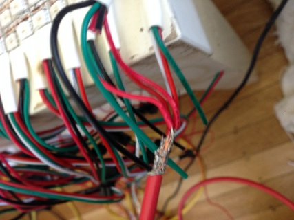
Thanks Ben, you have been a lot of help. In this picture, I soldered and twisted two 'in' power wires and two 'out' power wires from LED strips to a ticker wire that is going back to the supply. Does that sound like a good plan.
 
With "in" and "out" you mean wires from the two different ends of the strip? If yes, that's a good plan. How many LEDs will this thicker wire connect to? how long is the wire? You (we) can do some math / guesstimating to see if that will be ok.

That solder connection in the picture is bad, it seems the copper didn't get hot enough and the solder didn't properly flow. That easily happens with thick copper wires, as the heat from the iron is transferred away so quickly by the copper. And remember to use heat-shrink tubing to isolate the solder joint. Do not use electrical tape, as it will not last long, especially in warm environments (like with a few hundred LEDs nearby).
 
Each thicker wire is connected to a total of 452 LEDs (4x113). I plan to limit the brightness to 50% or so as the display will be inside.

The strips are in a zigzag pattern with each strip being 113 LEDs long. At the start, the first strip is connected to the thicker wire, the other end of that strip is connected to the next strip using the solderless connectors. When that strip gets back (#226 in the chain), it is connected to the ticker wire. The next strip is also connected to the thicker wire as it is an 'in.'

I will reflow the solder on that connection and, yes, I was planning to cover all the connections with heat shrink.
 
Understood. A rule of thumb is about 60mA per LED at full brightness, so at 50% brightness that's 30mA per LED. 0.03A * 452 = 13.56 Amps. Quite a lot. I'd go with at least 1.5mm² cabling. If you run the LEDs at full (50%) brightness, probe the voltage a the solderless connector. If it's to low, you should also attach cables there. I'm sorry I didn't mean to sound condescending with the solder/heatshrink. It's just hard to guess the level of expertise of people asking questions here, so I sometimes mention the basics just to be sure.
 
I did not take that as condescending. It is safe to assume that I don't know anything whenever you are replying to one of my posts.
 
Status
Not open for further replies.
Back
Top