Teensy 3.2 on Prop Shield

Status
Not open for further replies.

vvishwa

Member
Hi,

Halfway thru the page at http://www.pjrc.com/store/prop_shield.html which is basically "Audio Amplifier" section, I see that teensy is dropped into a socket soldered to prop shield. I got prop shield without pin, so presumbly I can plug teensy and get that to work. Unfortunately, this is not working. I am wondering if you could help to select right connector and I could avoid soldering.

Regards
V
 
Only a few of the Prop shield pins are in use - less when not using the hole thing. Those needed pins should be soldered/socketed though for reliable consistent behavior.
For Audio I see :: 5V-VIN/GND/3V/AMP/DAC-AudioIN to Teensy and then Speaker +/-
 
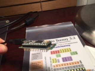
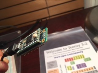
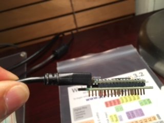
I am attaching picture and interested in motion sensors. Should I supply +5V, GND aafter soldering 5 IMG_8417.JPGIMG_8418.JPGIMG_8419.JPGpins?
 
Unfortunately, I can't tell from your pictures what is connected and what isn't.

The socket in the diagram is the 14x1 socket sold at the Teensy store (http://www.pjrc.com/store/socket_14x1.html), but you could use normal male headers (http://www.pjrc.com/store/header_14x1.html), or the double insulator pins created for the octows2812 shield (http://www.pjrc.com/store/header_14x1_d.html).

I have this google spreadsheet that lists the various pins used: https://docs.google.com/spreadsheet...ZridMGn-Yw2zyfYeeePysx2DKE/edit#gid=515300396.

For the motion sensors, you need to connect the i2c pins (A4/A5), in addition to the standard 3.3v, 5v, ground pins. IMHO, you probably should just connect all for the pins, but according to my notes, the following pins should be connected:
  • Ground pin
  • Pin 2 (for i2c interrupts)
  • Pin 5 (to enable the amplifier)
  • Pin 6 (to enable the 8 megabytes flash memory)
  • Pin 7 (for the LEDs)
  • Pin 11 (for SPI MOSI, and LED lights)
  • Pin 12 for (SPI MISO)
  • Pin 13 (for SPI SCLK and LED lights)
  • Pin 18/A4 (for i2c bus)
  • Pin 19/A5 (for i2c bus)
  • 3.3v
  • AGND (for audio output)
  • 5v VIN
  • Pin A14/DAT (for audio output)
 
Thanks MichaelMeissner, this definitely helped as made it clear exact reason for these pins on side. I used female socket on Prop Shield so that I can take Teensy out and plug into Generic Shield, it worked like charm! At the moment I am not using Audio as I wanted a good alternative of MX2125 from Parallel. Both in fact worked, however I see great potential in Teensy 3.2 as a nice combo of SPI and i2c. Probably a design blue print from Paul might give better insight.

Thanks a bunch
Vijay
 
Probably a design blue print from Paul might give better insight.

What specifically are you thinking? There's already a pinout diagram and schematic on the prop shield page (scroll down to Technical Details).

Would something else help? I probably can't do much until we're shipping the K66 boards... but I would like to improve the page in the future to clear up any confusion. Please let me know what improvements would have helped, and I'll put it on my to-do list.
 
Status
Not open for further replies.
Back
Top