Connecting 2 or more Teensy together with RS485

Status
Not open for further replies.

Tejkaran

Well-known member
Hi guys

So I have decided to connect my Teensys together with RS-485. I have made a start but not all is working smoothly.

The stuff I have read up on are:
RS 485 Wiring
Connections and circuitry needed
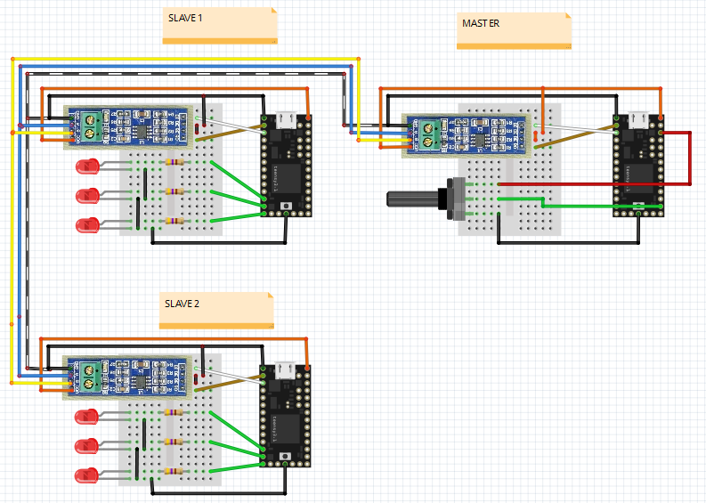
What the whole circuit should look like
Info about the RS85 transceiver
Teensy pins to use

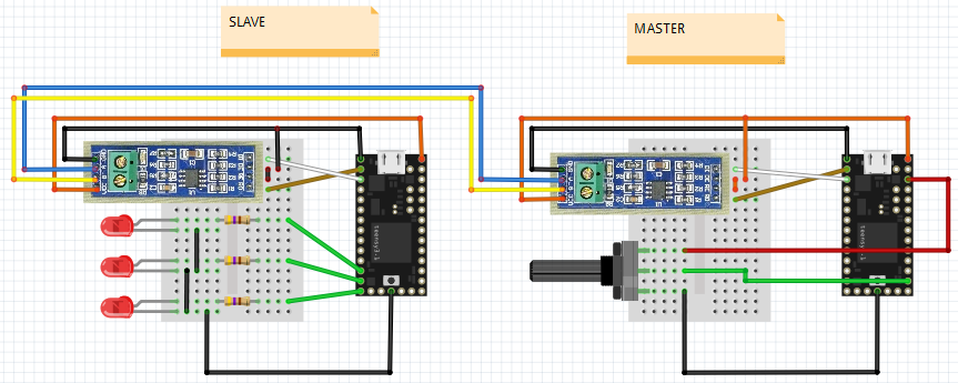
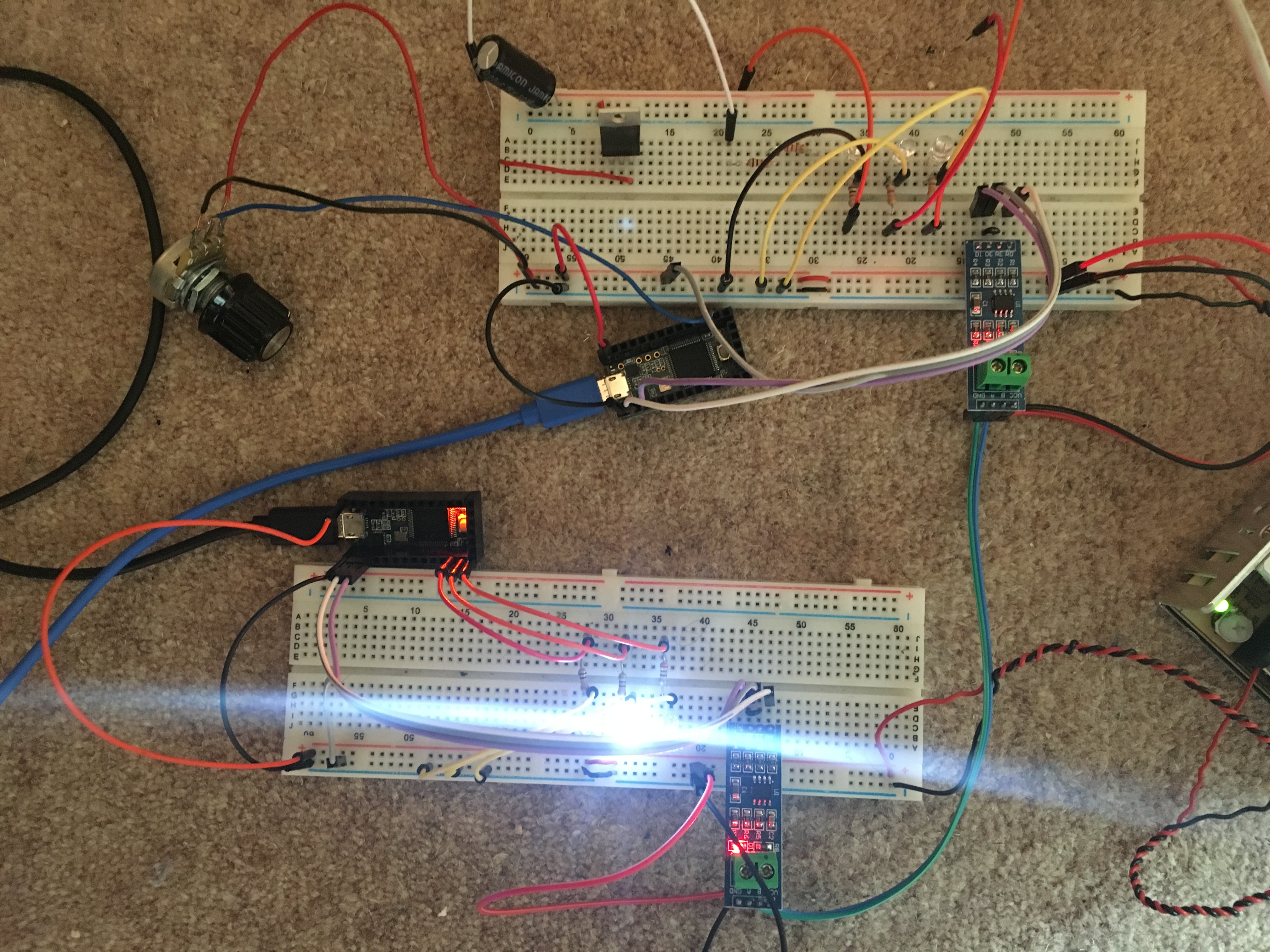
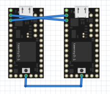
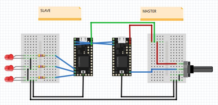
I think I have the circuit set up correctly
See image:
IMG_1226.jpg
(Ignore the loose wires on the left hand side of the top board)

Power (+ and -) is going from the Meanwell LRS-350-5(5V,60A) to 4 places.
1 - to the Master Teensy
2 - to the Slave Teensy
3 - to the top breadboard rail
4 - to the bottom breadboard rail

The top breadboard has the master Teensy(with the blue USB cable going into it/out) connected to the receiver
The transceiver has wires going to these pins on both of the Teensys (same for Master & Slave).
DI - Teensy pin 9
DE - Teensy pin 5
RE - connected to DE
RO - Teensy pin 10

The slave Teensy is the bottom one.

The transceivers are connected from A to A, and from B to B

Regarding the connections and wiring, does this all seem correct? Is there anything that needs changing?
I have not used any resistors because I think the transceivers already have 120R included so there is no need to attach further resistors, that is correct?

Second part, the coding
This is the current code I have:

Code:
#include <SoftwareSerial.h>
#define SSerialRX        9   //Serial Receive pin
#define SSerialTX        10  //Serial Transmit pin
#define SSerialTxControl 5   //RS485 Direction control
#define RS485Transmit    HIGH
#define RS485Receive     LOW
#define Pin13LED         13

SoftwareSerial RS485Serial(SSerialRX, SSerialTX); // RX, TX

int byteReceived;
int byteSend;

void setup()
{
  // Start the built-in serial port, probably to Serial Monitor
  Serial.begin(9600);
  Serial.println("YourDuino.com SoftwareSerial remote loop example");
  Serial.println("Use Serial Monitor, type in upper window, ENTER");
  
  pinMode(Pin13LED, OUTPUT);   
  pinMode(SSerialTxControl, OUTPUT);    
  
  digitalWrite(SSerialTxControl, RS485Receive);  // Init Transceiver   
  
  // Start the software serial port, to another device
  RS485Serial.begin(4800);   // set the data rate 
}

void loop()   /****** LOOP: RUNS CONSTANTLY ******/
{
  digitalWrite(Pin13LED, HIGH);  // Show activity
  if (Serial.available())
  {
    byteReceived = Serial.read();
    
    digitalWrite(SSerialTxControl, RS485Transmit);  // Enable RS485 Transmit   
    RS485Serial.write(byteReceived);          // Send byte to Remote Arduino
    
    digitalWrite(Pin13LED, LOW);  // Show activity    
    delay(10);
    digitalWrite(SSerialTxControl, RS485Receive);  // Disable RS485 Transmit       
  }
  
  if (RS485Serial.available())  //Look for data from other Arduino
   {
    digitalWrite(Pin13LED, HIGH);  // Show activity
    byteReceived = RS485Serial.read();    // Read received byte
    Serial.write(byteReceived);        // Show on Serial Monitor
    delay(10);
    digitalWrite(Pin13LED, LOW);  // Show activity   
   }  


/*-----( Declare User-written Functions )-----*/
 {
  digitalWrite(13, HIGH);   // turn the LED on (HIGH is the voltage level)
  delay(1000);               // wait for a second
  digitalWrite(13, LOW);    // turn the LED off by making the voltage LOW
  delay(1000);               // wait for a second
 }
}
//*********( THE END )***********

My user declared fuction bit of the code I have just done blink,
however, how would I tell the slave to blink?

there is a slave code as well which I have not really touched, it is like this:
Code:
#include <SoftwareSerial.h>
#define SSerialRX        9  //Serial Receive pin
#define SSerialTX        10  //Serial Transmit pin
#define SSerialTxControl 5   //RS485 Direction control
#define RS485Transmit    HIGH
#define RS485Receive     LOW
#define Pin13LED         13

SoftwareSerial RS485Serial(SSerialRX, SSerialTX); // RX, TX

int byteReceived;
int byteSend;

void setup()   /****** SETUP: RUNS ONCE ******/
{
  // Start the built-in serial port, probably to Serial Monitor
  Serial.begin(9600);
  Serial.println("SerialRemote");  // Can be ignored
  
  pinMode(Pin13LED, OUTPUT);   
  pinMode(SSerialTxControl, OUTPUT);  
  
  digitalWrite(SSerialTxControl, RS485Receive);  // Init Transceiver
  
  // Start the software serial port, to another device
  RS485Serial.begin(4800);   // set the data rate 
}//--(end setup )---


void loop()   /****** LOOP: RUNS CONSTANTLY ******/
{
  //Copy input data to output  
  if (RS485Serial.available()) 
  {
    byteSend = RS485Serial.read();   // Read the byte 
    
    digitalWrite(Pin13LED, HIGH);  // Show activity
    delay(10);              
    digitalWrite(Pin13LED, LOW);   
    
    digitalWrite(SSerialTxControl, RS485Transmit);  // Enable RS485 Transmit    
    RS485Serial.write(byteSend); // Send the byte back
    delay(10);   
    digitalWrite(SSerialTxControl, RS485Receive);  // Disable RS485 Transmit      
//    delay(100);
  }// End If RS485SerialAvailable
  
}//--(end main loop )---

/*-----( Declare User-written Functions )-----*/
//NONE

//*********( THE END )***********


All in all, I think the wiring is fine, but I am struggling with the code now
What do I need to do to make the Master tell the slave to operate blink for 1s intervals. I will expand upon that, but I feel this is a good start point.
I am decent with coding, but I have never communicated with another device before so this is new territory for me
 
EasyTransfer from Bill Porter is your friend... check it out...

After that, consider how to hand off messages from one to another. I ended up using a master/slave model in order to avoid collisions and other like issues. When only one unit is in charge, it is a lot easier to coordinate who does what without stomping on each others transmissions. Or, you could go full-duplex and not have to worry about collisions (2 more wires though).

Also, if you want to stay with the half-duplex configuration and you use Teensy's then I'd implement the serial Transmitter enable pin function as described on the UART page. Takes all the guesswork out of the enable pin, fully automatic and you don't risk cutting off a transmission before the serial buffer has been emptied of its payload.
 
Last edited:
Thanks for the wiring note HWGuy

@Constantin

I have downloaded and started using Bill Porters library, but I am kinda running around in the dark here.

So far what I would like is for this to happen(this is more to test my understanding of how the library works):
If I turn the potentiometer value from 0-333 LED 1 on the Slave turns on
If I turn the potentiometer value from 334-666 LED 2 on the Slave turns on
If I turn the potentiometer value from 667-1000 LED 3 on the Slave turns on
At the moment I have it set so if it is above 250, just LED 1 turns on.
However this is not happening, what am I doin

Code:
/*This is an example of the EasyTransfer Library 2way communications. 

The sketch is for the Arduino with a potentiometer attached to analog pin 0.

This other Arduino has the servo attached to pin 9.
Both have a putton attached to pin 12 and output a status using the LED on pin 13.

The idea is each arduino will read the status of the button attached to it, and send it
to the other Arduino, which will toggle it's LED based on the others button. The button 
should connect pin 12 to ground when pushed.

And the Arduino with the potentiometer will send it's value to the one with the servo.
The servo will move to the position based on the potentiometer.
*/


#include <EasyTransfer.h>

//create two objects
EasyTransfer ETin, ETout; 

int led1;
int led2;
int led3;
int SensorVal;

struct RECEIVE_DATA_STRUCTURE{
  //put your variable definitions here for the data you want to receive
  //THIS MUST BE EXACTLY THE SAME ON THE OTHER ARDUINO
int led1 = 7;
int led2 = 11;
int led3 = 13;
int SensorVal;
};

struct SEND_DATA_STRUCTURE{
  //put your variable definitions here for the data you want to receive
  //THIS MUST BE EXACTLY THE SAME ON THE OTHER ARDUINO
int led1 = 7;
int led2 = 11;
int led3 = 13;
int SensorVal;
};

//give a name to the group of data
RECEIVE_DATA_STRUCTURE rxdata;
SEND_DATA_STRUCTURE txdata;


void setup()
{
 Serial.begin(9600);
 //start the library, pass in the data details and the name of the serial port. Can be Serial, Serial1, Serial2, etc.
 ETin. begin(details(rxdata), &Serial);
 ETout.begin(details(txdata), &Serial);
  
 pinMode(led1, OUTPUT);   
 pinMode(led2, OUTPUT);   
 pinMode(led3, OUTPUT);     
}

void loop()
{
  //first, lets read our potentiometer and button and store it in our data structure
  txdata.SensorVal = analogRead(14);
  Serial.println(txdata.SensorVal);
    
  if(SensorVal>250) txdata.led3 = HIGH;
  
  //then we will go ahead and send that data out
  ETout.sendData();
  
 //there's a loop here so that we run the recieve function more often then the 
 //transmit function. This is important due to the slight differences in 
 //the clock speed of different Arduinos. If we didn't do this, messages 
 //would build up in the buffer and appear to cause a delay.
  for(int i=0; i<5; i++){
    //remember, you could use an if() here to check for new data, this time it's not needed.
    ETin.receiveData();
    
    //set our LED on or off based on what we received from the other Arduino    
    digitalWrite(13, rxdata.led3);
    digitalWrite(led3, HIGH);
    delay(1000);
    digitalWrite(led3, LOW);      
    
    //delay
    delay(200);
  }
//delay for good measure
delay(50);
}

i have quite a few questions, and if you could answer any/all of them I would be grateful:
1) What is the purpose of creating the objects 'ETIn' and 'ETOut'?

2) I have made the variables in my RECEIVE_DATA_STRUCTURE and SEND_DATA_STRUCTURE to be identical as it does not like it when they are not, any idea on why this is the case?

3) For the lines
Code:
 ETin. begin(details(rxdata), &Serial);
 ETout.begin(details(txdata), &Serial);
Do I need to specify something here. As in should I rename it, Serial and Serial 1 to identify between master and slave?

4) Do I need to put tx.data before everything i send, and rx.data for everything to receive on the slave?


I am getting random jibberish through at the moment on my master teensy
ending in the value of the potentiometer(0-1023)

5) Do I need to connect master, download the code to the master, then exactly same code to the slave, right?

Many, many thanks in advance for answers

Tej
 
Perhaps try first without the RS485 chips. Just connect the grounds, and a wire from one TX pin to the RX on the other Teensy, and vise versa.

Best to sort out the software-only data issues first using the simplest hardware. Then deal with the RS485 control.
 
Hey so I used this code below:


Code:
#include <EasyTransfer.h>

//create two objects
EasyTransfer ETin, ETout; 

int led1;
int led2;
int led3;
int sensorValue;

struct RECEIVE_DATA_STRUCTURE
{
//put your variable definitions here for the data you want to receive
//THIS MUST BE EXACTLY THE SAME ON THE OTHER ARDUINO
int led1 = 7;
int led2 = 11;
int led3 = 13;
int led4 = 22;
int sensorValue;
};

struct SEND_DATA_STRUCTURE
{
//put your variable definitions here for the data you want to send
//THIS MUST BE EXACTLY THE SAME ON THE OTHER ARDUINO
int led1 = 07;
int led2 = 11;
int led3 = 13;
int sensorValue;
};

//give a name to the group of data
RECEIVE_DATA_STRUCTURE rxdata;
SEND_DATA_STRUCTURE txdata;


void setup() //start the library, pass in the data details and the name of the serial port. Can be Serial, Serial1, Serial2, etc.
{
 Serial.begin(9600);
 ETin. begin(details(rxdata), &Serial);
 ETout.begin(details(txdata), &Serial);
 pinMode(led1, OUTPUT);   
 pinMode(led2, OUTPUT);   
 pinMode(led3, OUTPUT);     
}

void loop()
{
  //first, lets read our potentiometer and button and store it in our data structure
  txdata.sensorValue = analogRead(14); //this is the value of the potentiometer (and is stored in tx data??)
  Serial.print("Sensor Value Equals: "); 
  Serial.print(txdata.sensorValue);
  Serial.println("");
    
  if(txdata.sensorValue<250)
   {
    txdata.led1 =LOW;
    txdata.led2 =LOW;
    txdata.led3 =LOW;
   }
  else if(txdata.sensorValue>=250 && txdata.sensorValue<500)
   {
    txdata.led1 =HIGH;
    txdata.led2 =LOW;
    txdata.led3 =LOW;
   }
  else if(txdata.sensorValue>=500 && txdata.sensorValue<1000)
   {
    txdata.led1 =HIGH;
    txdata.led2 =HIGH;
    txdata.led3 =LOW; 
   }
  else if(txdata.sensorValue>=1000)
   {
    txdata.led1 =HIGH;
    txdata.led2 =HIGH;
    txdata.led3 =HIGH;    
   }
  
  //then we will go ahead and send that data out
  ETout.sendData();
  
 //there's a loop here so that we run the recieve function more often then the 
 //transmit function. This is important due to the slight differences in 
 //the clock speed of different Arduinos. If we didn't do this, messages 
 //would build up in the buffer and appear to cause a delay.
  for(int i=0; i<5; i++){
    //remember, you could use an if() here to check for new data, this time it's not needed.
    ETin.receiveData();
    
    //set our LED on or off based on what we received from the other Arduino    
    digitalWrite(led1, rxdata.led1);
    digitalWrite(led2, rxdata.led2);
    digitalWrite(led3, rxdata.led3);   
    
    //delay
    delay(50);
  }
  
  //delay for good measure
  delay(50);
}

and when i try to use the main part of the logic on one Teensy, to make sure that as I adjust the potentiometer, that the lights tunr on/off, it works.

My issue seems to be with connecting two Tennsy together.
So if I try with TX/RX or with RS485 nothing seems to be working. any idea what I am doing wrong?
 
A few remarks...

---
led1, led2, led3 are not initialized with a pin number.
---
RECEIVE_DATA_STRUCTURE and SEND_DATA_STRUCTURE are not the same
---
RS485: I can not see how you control the DE/RE pin from the RS485 transceiver
---
Code:
 ETin. begin(details(rxdata), &Serial);
 ETout.begin(details(txdata), &Serial);
Serial is the emulated USB Serial connection to the computer. For the serial connection (e.g. RS485) it can be one of the hardware serial ports: Serial1, Serial2 or Serial3
---
If you try without the RS485 transceivers; RX and TX between the two Teensy should be crossed.
sy8Bv43.png


Here is an example. One Teensy is the Master with the sensor input (potentiometer). The 2nd Teensy is the Slave with the 3 leds.

  • connect everything according to the diagram below
  • connect the Master Teensy to the computer, program it with the Master sketch
  • disconnect the usb cable
  • connect the Slave Teensy to the computer, program it with the Slave sketch
  • optional: open the serial monitor window, it shows the sensor value
  • turn the potentiometer

(If you want to connect both Teensy to the computer at the same time: remove the green wire.)

wiring
YHjfUNr.png


code


Master

Code:
#include <EasyTransfer.h>

EasyTransfer ETout; 

int sensorInput = A0;

struct SEND_DATA_STRUCTURE
{
  //put your variable definitions here for the data you want to send
  //THIS MUST BE EXACTLY THE SAME ON THE OTHER ARDUINO
  int sensorValue;
};

//give a name to the group of data
SEND_DATA_STRUCTURE txdata;


void setup() //start the library, pass in the data details and the name of the serial port. Can be Serial1, Serial2, Serial3.
{
  Serial.begin(9600); // start usb serial
  Serial1.begin(9600); 
  ETout.begin(details(txdata), &Serial1); // start easytransfer with Serial1
  pinMode(sensorInput, INPUT);  
}

void loop()
{
  //first, lets read our potentiometer and store it in our data structure
  txdata.sensorValue = analogRead(sensorInput); //this is the value of the potentiometer (and is stored in tx data)
  Serial.print("Sensor Value Equals: "); 
  Serial.println(txdata.sensorValue);
  
  //then we will go ahead and send that data out
  ETout.sendData();
 
  delay(50);
}

Slave
Code:
#include <EasyTransfer.h>

EasyTransfer ETin; 

int led1 = 10;
int led2 = 11;
int led3 = 12;

struct RECEIVE_DATA_STRUCTURE
{
  //put your variable definitions here for the data you want to receive
  //THIS MUST BE EXACTLY THE SAME ON THE OTHER ARDUINO
  int sensorValue;
};

//give a name to the group of data
RECEIVE_DATA_STRUCTURE rxdata;

void setup() {//start the library, pass in the data details and the name of the serial port. Can be Serial1, Serial2, Serial3.
  Serial.begin(9600);
  Serial1.begin(9600);
  ETin.begin(details(rxdata), &Serial1);
  pinMode(led1, OUTPUT);   
  pinMode(led2, OUTPUT);   
  pinMode(led3, OUTPUT);     
}

void loop() {
  if(ETin.receiveData()) {
    Serial.print("Receive Sensor Value: "); 
    Serial.println(rxdata.sensorValue);
    //set our LED on or off based on what we received from the other Arduino   
    if(rxdata.sensorValue < 250) {
      digitalWrite(led1, LOW);
      digitalWrite(led2, LOW);
      digitalWrite(led3, LOW);
    } else if(rxdata.sensorValue < 500) {
      digitalWrite(led1, HIGH);
      digitalWrite(led2, LOW);
      digitalWrite(led3, LOW);
    } else if(rxdata.sensorValue < 1000) {
      digitalWrite(led1, HIGH);
      digitalWrite(led2, HIGH);
      digitalWrite(led3, LOW); 
    } else {
      digitalWrite(led1,HIGH);
      digitalWrite(led2, HIGH);
      digitalWrite(led3, HIGH);    
    } 
  }
}
 
Last edited:
Thanks HWGuy!
I have the TX RX working now and that is a good start. Allieved a lot of annoyance which has been building up as I could not get it too work, so thank you :)

Regarding the rS485 bit, you say:
RS485: I can not see how you control the DE/RE pin from the RS485 transceiver

and the reason is that I don't know what to do for that...
how would I begin coding it. Really have no idea here?!?!

In the meanwhile, I will play around with stuff and see how my (bad) code compares with yours so I can understand what I was doing wrong...
the first thing was that I had the same code for both Master and Slave as I thought the code had to be identical...I'm learning still...


---
Generally speaking I think I have an understanding of what has happened now. So you have to separate the Master and Slave into two different scripts, which I did not have before. So, you have SEND_DATA_STRUCTURE for the master as it is sending stuff, and RECEIVE_DATA_STRUCTURE for the slave as it receives stuff. It is so obvious i feel silly now!
The rxdata and txdata groups I am a bit hazy on. So if we have the line such as:
Code:
    if(rxdata.sensorValue < 250)
what is the purpose of the rxdata there? Are we saying have a look at data coming in specifically labelled sensorValue? If you changed that to a txdata, I assume that would look at the group for txdata. Is my understanding right here?

I understand the difference between Serial & Serial1, Serial2 etc. now. I know someone in the past mentioned something but it went over my head, because previously I was using Serial on its own so it was talking to the USB, not the other Teensy via the Serial1.


EDIT: added from the dashed lines
 
Last edited:
RS-485 defines the electrical characteristics, the software layer is up to the maker. One simple approach is a single master with one or more slaves. The master is in control, he sends and requests data from the slaves, the slaves only respond after a request.
The RS-485 module linked in the first post is a half-duplex module. It provides RS-485 communication in both directions, but only one direction at a time. DE (driver enable) and RE (receiver enable) set the direction.
In the current project, the master always sends data (the sensor/potentiometer value) to the slave, the slave never sends data back to the master. We don't need to change the communication direction -> we can hardwire the direction pins.

VCC for the RS-485 module is 5V.
MXSmfAU.png

This should work with the code from my last post.

Later, when slaves send data back to the master, DE and RE are controlled with a Teensy pin and the function Serial1.transmitterEnable(pin)
https://www.pjrc.com/teensy/td_uart.html
https://i.imgur.com/T7cfGjf.png

rxdata is a struct which contains the received data from the RS-485 bus, in our example it's filled with a single integer sensorValue.
The incoming data is a stream of bits (or bytes). Nothing is labeled with sensorValue. But we know the structure of the received data, the first 4 bytes (=signed integer) are for sensorValue. Thats why SEND/RECEIVE_DATA_STRUCTURE in both sketches must be the same.

The example code lacks the ability to send data back from the slave to the master and a system to address a specific slave in a RS-485 network with more than one slave. (This is all done in software).
 
Ok, the Rs-485 thing makes sense. So using DE data is sent, and RE data is receieved, or in state to send/receive right?
When you talk about hard wiring the direction pins, what is meant by that? Are you saying (for example) that we call pin 0 to always be DE and pin 1 to be RE? I'm not so sure I understand that bit.

rxdata bit makes sense now, top man

and finally, the current circuit layout did not work for me. I assume it is the circuit and not the code because when I swapped back to TX/RX Teensy to Teensy lines it worked fine. Should the wire which is attached to DE/RE be connected to some other pin on the Teensy rather than V++(for master) & V--(for slave)? That doesn't quite seem right to me (and my novice mind)?
 
Should the wire which is attached to DE/RE be connected to some other pin on the Teensy rather than V++(for master) & V--(for slave)? That doesn't quite seem right to me (and my novice mind)?

If you only send data in 1 direction, this is correct. Some protocols like DMX are always data in the same direction.

For protocols where the slave devices transmit replies, you need both sides to have DE/RE controlled by a pin.
 
The RS-485 transceiver contains a driver and a receiver. You either activate the driver or the receiver. This is done with the DE (Driver Output Enable) and RE (Receiver Output Enable) pins. Note that on chip level, the RE input is inverted logic. The data itself is sent trough the DI (Driver Input) pin or received from the RO pin (Receiver Output).

With hardwire I meant that RE/DE is connected to V++ or V-- and not controlled by a digital pin from the Teensy.

the current circuit layout did not work for me
both Teensies (+RS-485 modules) are powered on?

I'll try to rebuild the circuit later, but the circuit should work.

... maybe upload a picture from the circuit
 
Last edited:
@Paul Stoffregen, thanks for the info. I had no idea about that
@HWGuy
Ah right, so by activate DE or RE and as a result of that the DI or RO can be utilised?

Both Teensies are powered

sorry about the massive pic, not sure how to trim it down.
Top one is the Master
Bottom one is the slave
Potentiometer is on the top left, connnected to power rail and Teensy pin 14 (Pot works fine)

On the master and slave RS485 transceiver it is Purple wire from DI, Grey from DE.RE and White from RO.
White to pin 0, Purple to pin 1 and Grey to V++ power rail for Master and V-- for Slave
LED pins, 10,11,12
Transceiver, Vcc to V++ rail, GND to V--rail. A to A and B to B


tlQ6S4j.jpg
 
the wiring looks good.

why is the led on the Teensy on? It's not used in the code.
One led pin 10, 11 or 12 is on, they shouldn't light up without data over RS 485.

The red wire from the Potentiometer goes to the 3.3V pin (and not VIN). But this isn't the problem.

Are the usb cables plugged in a computer? If so:
- remove all wires to the the Meanwell power supply
- disconnect both usb cables
- connect both usb cables
- open serial monitor for the slave

I've set it up here, it works with the code from post #7 and wiring from post #9. I don't have the same RS 485 modules. Both RS 485 Transceivers are similar to the one on your modules. A picture won't help much, but maybe you can see something: (I don't have a potentiometer, I use a floating wire): https://dl.dropboxusercontent.com/u/2486346/pjrc/rs 485.pdf

so by activate DE or RE and as a result of that the DI or RO can be utilised?
yes
 
Not really sure why the light was on for the Teensy, after re-wiring all the wires but it is no longer turned on.
Followed the steps you said and my conclusion is that there seems to be an error with sending the signal from the Master to Slave.
The reason I've come to this conclusion is that when I open the Serial Monitor for Master it says "Sensor Value Equals: xxxx" However when I open the slave it does not say "Receive Sensor Value: xxxx". It is just blank with nothing on the Serial Monitor.

I'm just going to play around/change the wires to see if something is maybe wrong with the wires here?

Changed all the wires and the transceivers with no change...bit stumped now...
 
Last edited:
maybe, the tiny jumper wires for DE/RE don't make a reliable connection.

If you have a voltmeter you can check the DE and RE pins. With an oscilloscope you could check RS 485 A and B.
 
CngRzVU.jpg


I got it working.
I changed everything, so the two Teensy's, the two transceivers and made sure all the wires were working....the problem....one of the transceivers was not working properly.
So annoying when it is such a little thing...
One other thing though, my master transceiver is hot to touch? Should this be the case/of concern?

quite happy now :) :) :)

and then straight into serious mode again
what would be the way to connect three Teensy together now?
The things I am aware of that I need to think of
- With the transceivers they have 120Ohm resistors embedded which means I would need to remove the resistor for middle one in a series,
I would need to name(?) my Teensys so the data knows where it needs to go/when i gets to the correct teensy it would accept it.

Really do want to say thank you to you HWGuy, you've got me this far. I promise once I know how to do the three together I should be done...for now,lol.
 
For multiple slaves:
Extend the *_DATA_STRUCTURE with an additional parameter for the address (slaveId). In the slave code, set the address for the slave (#define SLAVE_ID 1) and check if the received data is for this slave (slave address = address in received data).

the example code is a bit silly, slave 1 works like before and slave 2 always receives sensorValue=850.

master
Code:
#include <EasyTransfer.h>

EasyTransfer ETout; 

int sensorPin = A0;

struct SEND_DATA_STRUCTURE
{
  //put your variable definitions here for the data you want to send
  //THIS MUST BE EXACTLY THE SAME ON THE OTHER ARDUINO
  [B]int slaveId;[/B]
  int sensorValue;
};

//give a name to the group of data
SEND_DATA_STRUCTURE txdata;


void setup()
{
  // start the usb serial emulation
  Serial.begin(9600); // start usb serial
  // start the hardware serial for the RS-485 bus
  Serial1.begin(9600); 
  ETout.begin(details(txdata), &Serial1); // start easytransfer with Serial1
  pinMode(sensorPin,INPUT);  
}

void loop()
{
  /*
    send to slave with address 1
  */
  // set the slave address
  [B]txdata.slaveId = 1; [/B] 
  //lets read our potentiometer and button and store it in our data structure
  txdata.sensorValue = analogRead(sensorPin); //this is the value of the potentiometer and is stored in txdata
  Serial.print("Sensor Value Equals: "); 
  Serial.println(txdata.sensorValue);
  
  //then we will go ahead and send that data out
  ETout.sendData();

  /*
    send to slave with address 2
  */
  [B]txdata.slaveId = 2; [/B] 
  txdata.sensorValue = 850;
  ETout.sendData();
 
  delay(50);
}

slave 1

Code:
#include <EasyTransfer.h>

[B]#define SLAVE_ID 1[/B]

EasyTransfer ETin; 

int led1 = 10;
int led2 = 11;
int led3 = 12;

struct RECEIVE_DATA_STRUCTURE
{
  //put your variable definitions here for the data you want to receive
  //THIS MUST BE EXACTLY THE SAME ON THE OTHER ARDUINO
[B]  int slaveId;[/B]
  int sensorValue;
};

//give a name to the group of data
RECEIVE_DATA_STRUCTURE rxdata;

void setup() {//start the library, pass in the data details and the name of the serial port. Can be Serial1, Serial2, Serial3.
  // start the usb serial emulation
  Serial.begin(9600);
  // start the hardware serial for the RS-485 bus
  Serial1.begin(9600); 
  ETin.begin(details(rxdata), &Serial1);
  pinMode(led1, OUTPUT);   
  pinMode(led2, OUTPUT);   
  pinMode(led3, OUTPUT);     
}

void loop() {
  // is RS 485 data available?
  if(ETin.receiveData()) {
    // check if the message is for this slave	
[B]    if(rxdata.slaveId == SLAVE_ID) {[/B]
      // print the received data to the usb serial port
      Serial.print("Id: "); 
      Serial.print(rxdata.slaveId);
      Serial.print(" Sensor Value: ");
      Serial.println(rxdata.sensorValue);
      //set our LED on or off based on what we received from the other Arduino   
      if(rxdata.sensorValue < 250) {
        digitalWrite(led1, LOW);
        digitalWrite(led2, LOW);
        digitalWrite(led3, LOW);
      } else if(rxdata.sensorValue < 500) {
        digitalWrite(led1, HIGH);
        digitalWrite(led2, LOW);
        digitalWrite(led3, LOW);
      } else if(rxdata.sensorValue < 1000) {
        digitalWrite(led1, HIGH);
        digitalWrite(led2, HIGH);
        digitalWrite(led3, LOW); 
      } else {
        digitalWrite(led1, HIGH);
        digitalWrite(led2, HIGH);
        digitalWrite(led3, HIGH);    
      } 
[B]    }[/B]
  }
}

slave 2
only difference to slave 1 is #define SLAVE_ID 2

Code:
#include <EasyTransfer.h>

[B]#define SLAVE_ID 2[/B]

EasyTransfer ETin; 

int led1 = 10;
int led2 = 11;
int led3 = 12;

struct RECEIVE_DATA_STRUCTURE
{
  //put your variable definitions here for the data you want to receive
  //THIS MUST BE EXACTLY THE SAME ON THE OTHER ARDUINO
[B]  int slaveId;[/B]
  int sensorValue;
};

//give a name to the group of data
RECEIVE_DATA_STRUCTURE rxdata;

void setup() {//start the library, pass in the data details and the name of the serial port. Can be Serial1, Serial2, Serial3.
  // start the usb serial emulation
  Serial.begin(9600);
  // start the hardware serial for the RS-485 bus
  Serial1.begin(9600); 
  ETin.begin(details(rxdata), &Serial1);
  pinMode(led1, OUTPUT);   
  pinMode(led2, OUTPUT);   
  pinMode(led3, OUTPUT);     
}

void loop() {
  // is RS 485 data available?
  if(ETin.receiveData()) {
    // check if the message is for this slave	
[B]    if(rxdata.slaveId == SLAVE_ID) {[/B]
      // print the received data to the usb serial port
      Serial.print("Id: "); 
      Serial.print(rxdata.slaveId);
      Serial.print(" Sensor Value: ");
      Serial.println(rxdata.sensorValue);
      //set our LED on or off based on what we received from the other Arduino   
      if(rxdata.sensorValue < 250) {
        digitalWrite(led1, LOW);
        digitalWrite(led2, LOW);
        digitalWrite(led3, LOW);
      } else if(rxdata.sensorValue < 500) {
        digitalWrite(led1, HIGH);
        digitalWrite(led2, LOW);
        digitalWrite(led3, LOW);
      } else if(rxdata.sensorValue < 1000) {
        digitalWrite(led1, HIGH);
        digitalWrite(led2, HIGH);
        digitalWrite(led3, LOW); 
      } else {
        digitalWrite(led1, HIGH);
        digitalWrite(led2, HIGH);
        digitalWrite(led3, HIGH);    
      } 
[B]    }[/B]
  }
}

wiring

the wiring is similar as before, connect RS 485 A and B. Another topic is whether the RS485 bus needs a common ground connection or not. Texas Instrument writes:

Grounding and Shielding
Although the potential difference between the data-pair conductors determines the signal without officially
involving ground, the bus needs a ground wire to provide a return path for induced common-mode noise
and currents, such as the receivers' input current. A typical mistake is to connect two nodes with only two
wires. If you do this, the system may radiate high levels of EMI, because the common-mode return current
finds its way back to the source, regardless of where the loop takes it. An intentional ground provides a
low-impedance path in a known location, thus reducing emissions.
Electromagnetic-compatibility and application requirements determine whether you need a shield. A shield
both prevents the coupling of external noise to the bus and limits emissions from the bus. Generally, a
shield connects to a solid ground (normally, the metal frame around the system or subsystem) with a low
impedance at one end and a series RC network at the other. This arrangement prevents the flow of DC
ground-loop currents in the shield.

AN-1057 Ten Ways to Bulletproof RS-485 Interfaces http://www.ti.com/lit/an/snla049b/snla049b.pdf
Another good read is: The RS-485 Design Guide http://www.ti.com/lit/an/slla272b/slla272b.pdf


ZV46QJV.png
 
Hey HWGuy
got it all sorted first go, thank you ever so much for that!
thanks for the reads too.

Only a thought, not an action, but I may need to have it so Slaves can send back to master in the half duplex method you mentioned above. Would this require a lot more work/wiring?

I'm gonna play around with this for a bit. I am away from thurs till Monday, so excuse me if i don't reply promptly to anything said
 
The wiring is nearly the same. The difference: DE/RE is controlled by a digital pin.
Code is more complex, but definitely doable.

I can post an example until Monday.
 
That is absolutely fine.
Just out of interest more than anything else, what is your job? Or are you a really good enthusiast?
 
I have an education in the electronic field (the education system here is a bit different than in UK/USA) and worked a few years in electronics manufacturing. I currently do software support/administration (no hardware or software developement involved).
 
I did not forget this thread. Tried to setup an example but it did not work as expected. I am still working on it...
 
Status
Not open for further replies.
Back
Top