FreqMeasure Inconsistency in Optical Tachometer

Status
Not open for further replies.

trent

Member
I'm trying to use the FreqMeasure library to measure the shaft speed of a motor, and received a bit of help from the forum earlier pertaining to the circuitry necessary to get a good, clean digital signal. Now I have a nice signal and I am getting readings in the right ballpark. I am now wondering what might be causing about 1-3 Hz of error in the readings.
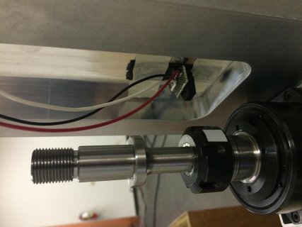
Here is my setup:
000014.jpg

And here is the signal in green after filtering and using a Schmitt trigger (signal in purple is after filtering alone). Low is 0V and high is 3.1V:
000012.jpg

My signal (seen on the scope) is really clean, and the scope's frequency reading only varies by about .3 Hz max. So I'm also pretty confident that the motor is keeping its speed constant.

I am using the Serial_Output example, and have tried to increase the number of samples taken before a reading is given. Here is the output (the first number is RPM, the second is Hz):
000013.png

Interestingly, increasing the number of samples taken before outputting the frequency (from 30 to 100, even to 900) does not make the readings more acccurate.

Should this amount of variation be expected? Is 30Hz too quick for the Teensy? I know basically how the FreqMeasure library works, but not enough to know how this problem could be happening.
 

Attachments

  • IMG_7078.jpg
    IMG_7078.jpg
    95.3 KB · Views: 129
The FreqMeasure library should give a variation of one processor bus clock pulse. Of course there are variations on the exact point of the filtered signal where the Schmitt trigger, as you see on the scope this was around 0.3 Hz. So something else is going on. I can think of some possible scenarios:

There is a section in your program where interrupts are turned of so that the overflow counting in the FreqMeasure library misses one overflow, this would give a count error of 65536.

For some reason the Teensy fails to detect the rising edge of your signal, this would give a lower measured frequency, and some events having almost double number of counts.

There are still noise on the Shmitt trigger signal, faster than you can visually see on the scope, that triggers extra events with very few counts.

You can check for these different situations by printing the exact counts for a few hundred events. Look at the returned counts, dont even bother converting to frequency.
 
There is also a digital filter on the input capture pin that I think can be activated in the setup by using:

Code:
  /* Activate input capture filter for FTM1 CH 0 */
  FTM1_FILTER = 0xF;
  /* Start frequency measurement */
  FreqMeasure.begin();
 
There is also a digital filter on the input capture pin that I think can be activated in the setup by using:

Code:
  /* Activate input capture filter for FTM1 CH 0 */
  FTM1_FILTER = 0xF;
  /* Start frequency measurement */
  FreqMeasure.begin();

Maybe consider a 1kOhms, 10nF low pass after the schmitt (~160Hz fc).

Thanks, I'm gonna try both of these things and report back.
 
Did the filtering work?

If not, please post the exact code you're running, even if it's only a trivial change from the serial output example. I'll try running it here with a function generator set to 30 Hz.
 
Did the filtering work?

Yes, I started using a dedicated Shmitt trigger chip (74HC14N) after a LPF with fc = ~500 Hz, and it rails better than my comparator circuit. Here is my new signal, which goes from 0V to 2.06V:
4OnnwzG.jpg


However, things are still a little quirky. Weirdly, FreqMeasure just stopped working for me. I tried a lot of things, and this was my code at the end (I took out all the averaging).

Code:
/* FreqMeasure - Example with serial output
 * http://www.pjrc.com/teensy/td_libs_FreqMeasure.html
 *
 * This example code is in the public domain.
 */
#include <FreqMeasure.h>

void setup() {
  Serial.begin(57600);
  FreqMeasure.begin();
}

void loop() {
  if (FreqMeasure.available()) {
      float frequency = FreqMeasure.countToFrequency(FreqMeasure.read());
      Serial.println(frequency);
    }
}

Let me remind you that FreqMeasure is limited to getting a signal on pin 13, and I could see my signal triggering the onboard LED. I tried this with two Teensies with no luck. I was afraid I had burned out Pin 13, but it still works as the SPI CLK for my SD card.

However, FreqMeasureMulti worked perfectly for me. It's available on different pins, so I was trying it out on the A8-9 pins, and it gave me better results than I've ever had (I couldn't try it out on pin 13 because the library is not compatible with frequency measurement on that pin):

CZM1CDQ.png

For the code, I used the Serial_Output example of the FreqMeasureMulti library, replacing only lines 19-21 with

Code:
  freq1.begin(6);
  freq2.begin(22);
  freq3.begin(23);


This is perfect for me, and it's probably what I will use; I'm just wondering why FreqMeasureMulti would work differently/better than FreqMeasure?
 
Last edited:
Status
Not open for further replies.
Back
Top