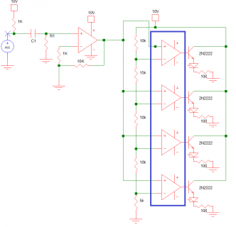
The circuit below is supposed to turn on a LED when the microphone input reaches these levels:
1V, 3V, 5V, 7V.
What this circuit does in real life is when we turn on the power, all 4 LEDs light up.
When we remove the mic amplifier, it doesn't power up the LEDs since it only produces mV.
When we changed the amplifier gain, it lights up 2-3 LEDs but speaking to the microphone doesn't turn on the remainng LEDs.
Our instructor suggested that the impedance of the microphone and our circuit does not match. Is that the reason or can any other fix be done?
The OP-Amps inside the indigo box is part of a LM324 IC while the outside Op-Amp is a 741 IC.
Any suggestions will be much appreciated!


