K64 Beta Test :: Teensy 3.5

Status
Not open for further replies.

defragster

Senior Member+
As seen on Kickstarter: kickstarter _ paulstoffregen _ teensy-35-and-36

A few Beta T_3.5 units arrived in the world 8/31/16 - This thread for related general posts. While the K66 and K64 are greatly similar, starting this new thread as the old one has months of history and while similar, notes here may be K64 specific.

the Teensy 3.5 K64 is __MK64FX512__ [ corresponding ID for Teensy 3.6 K66 board is __MK66FX1M0__ ]

Preliminary Eagle footprint Library For KS Teensy 3.5/3.6, Another Eagle Teensy drawing and Another version Eagle Library - includes prior Teensy 3 and LC
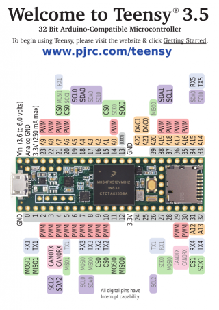
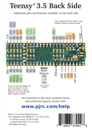
KS_T_3.5f.PNGKS_T_3.5b.PNG T_3.6_3.3V_NOTE.PNG
Kickstarter packages will include a card like this with each Teensy NOTE: the inset detail on the backside, the cards shipping with KS Rewards erroneously suggest 5V, above it properly shows 3.3V on the indicated analog pins.

This thread is a parallel partner to the K66 T_3.6 thread located here:: forum.pjrc.com/threads/34808-K66-Beta-Test

The Teensy 3.5 is a 5 volt tolerant [ on digital I/O pins ] part, similar to the Teensy 3.2. Many notes here may apply to the linked K66 thread above - but not all, see below for up front differences.

Datasheets K64 (5V tolerant):
K64 Data Sheet (electrical specs): data_sheet/K64P144M120SF5.pdf
K64 Reference Manual (programming specs: ref_manual/K64P144M120SF5RM.pdf

Teensy 3.5 Features:
•120 MHz ARM Cortex-M4 with Floating Point Unit
•512K Flash, 192K RAM, 4K EEPROM
•Microcontroller Chip MK64FX512VMD12 (PDF link)
•1 CAN Bus Port
•16 General Purpose DMA Channels
•5 Volt Tolerance On All Digital I/O Pins

•62 I/O Pins (42 breadboard friendly)
•25 Analog Inputs to 2 ADCs with 13 bits resolution
•2 Analog Outputs (DACs) with 12 bit resolution
•20 PWM Outputs
•USB Full Speed (12 Mbit/sec) Port
•Ethernet mac, capable of full 100 Mbit/sec speed
•Native (4 bit SDIO) micro SD card port
•I2S Audio Port, 4 Channel Digital Audio Input & Output
•14 Hardware Timers
•Cryptographic Acceleration Unit
•Random Number Generator
•CRC Computation Unit
•6 Serial Ports (2 with FIFO & Fast Baud Rates)
•3 SPI Ports (1 with FIFO)
•3 I2C Ports
•Real Time Clock [Ships with crystal installed]

Major differences T_3.5 w/K64 versus T_3.6 w/K66
T_3.5 :: NO Touch Sensing Inputs
ARM Cortex-M4 w/FPU :: T_3.5 rated at 120 MHz versus T_3.6 180 MHz
RAM :: T_3.5 192K RAM versus T_3.6 256K RAM
FLASH :: T_3.5 512K Flash versus T_3.6 1M Flash
ON T_3.5 ( K64 ) 5V tolerance On All Digital I/O Pins - SEE FINAL DOCS FOR DETAILS!
ON T_3.6 only the VIN pin is designed to get over 3.3V - SEE FINAL DOCS FOR DETAILS!
I2C :: Teensy 3.5 has 3 I2C ports, and four on T_3.6
 
Last edited:
{ I copied and generalized these features to perhaps put sticky links ? }

Common features may be linked from this post : K66-Beta-Test

Technical Features & Specifications
• ARM Cortex-M4 with Floating Point Unit
• Flash, RAM, 4K EEPROM
• Microcontroller Chip ( MCU )
• CAN Bus
• General Purpose DMA Channels
• PWM Outputs
• I2C Ports

UNIQUE ELEMENTS TO EACH::
[• T_3.6 Touch Sensing Inputs]
[• T_3.6 USB High Speed (480 Mbit/sec) Port]
[• T_3.5 5 Volt Tolerance On All Digital I/O Pins]

• 62 I/O Pins (42 breadboard friendly)
• 25 Analog Inputs to 2 ADCs with 13 bits resolution
• 2 Analog Outputs (DACs) with 12 bit resolution

• USB Full Speed (12 Mbit/sec) Port
• Ethernet mac, capable of full 100 Mbit/sec speed
• Native (4 bit SDIO) micro SD card port
• I2S Audio Port, 4 Channel Digital Audio Input & Output
• 14 Hardware Timers
• Cryptographic Acceleration Unit
• Random Number Generator
• CRC Computation Unit
• 6 Serial Ports (2 with FIFO & Fast Baud Rates)
• 3 SPI Ports (1 with FIFO)
• 3 I2C Ports (Teensy 3.6 has a 4th I2C port)
• Real Time Clock [Ships with crystal installed]
 
Last edited:
Thanks Defragster,

Should also mention, that lots of information about this beta is up on the thread: https://forum.pjrc.com/threads/34808-K66-Beta-Test, including datasheets and some pinouts,

I also have verified that Blink works. Next up to solder on pins and the like so I can test Serial6-1...

I also new believe that the 5 pin header for USB host connections are not wired up at all on the T3.5 so what I wondered earlier if the cooresponding pins on the K64 which appear to be Analog pins would be available here. My first inspection says, probably not.
 
Thanks Defragster,

I also new believe that the 5 pin header for USB host connections are not wired up at all on the T3.5 so what I wondered earlier if the cooresponding pins on the K64 which appear to be Analog pins would be available here. My first inspection says, probably not.

:) - just hoping to be helpful . . . the first posts are TBD if this works to get to announcements - just wanted to make a placeholder ASAP . . .

I see traces to D+ and D- and the two GND are there - the 5V is missing because the components are pulled to supply/route power? I assume the BOARD is the same PCB?
 
I guess sticker, saying which type it is, would be helpful. The 3.5 and 3.6 look very similar..

I will solder pins to my 3.5 tomotrrow and do more tests, then.
 
Paul,

As per your request, first thing I did was to solder on lots of pins. including those that Serial6 is on.

Had to make some fixes like define new clock gate in the kinetis.h
Then updated all of the places that were still referring to the Uart4 gate to use the new uart5 gate. Plus fixed casing in the name for the ISR.

Now my simple Test is at least working for output. Will continue to test.

Current fixes are up in pull request: https://github.com/PaulStoffregen/cores/pull/169

Kurt
 
After the kickstarter supporter rewards have been shipped, how long until PJRC able to enter 'normal' production availability for the T3.5?
Comparative board input power (mAH?) data for T3.5 at a given clock rate available (will not use the PMC) with chip in 'normal run' mode and core mode in 'run'? Could not find useful date in ref manual or AN4503.

Kind and warm regards to the all for their efforts in supporting my employer's pursuit of ruthless and crass capitalism.
 
K64 beta testing teensy 3.5 sticky post (i'll update this with my testing results)

IDE 1.6.11 1.30-beta3 on ubuntu 14.04, testing @120MHz unless otherwise stated

getuid 128-bit UniqueID from chip: 0018FFFF FFFFFFFF 4E453130 30190004
getmac (64 bit) 4E9E5 339DE (last is USB id, lsusb -v id 2114220 (x10)

RTC working.

K64 crystal drift tests
Code:
          crystal drift (ppm)   (specs: ? 16mhz 18ppm   32khz ?ppm)
 crystal    K66 proto  K66 beta3   K64 beta
MCU 16mhz       8          -6        -19
RTC 32khz       0          -6        -11

Power tests with delay(5000) in loop(), also have power for adding asm("wfi") to yield.cpp (called by delay())
measured with hacked USB cable. Why is K64 consuming more power than K66? :confused:
Code:
        loop/delay(5000) power (ma)
             K66              K64          T3.2
clock   default   WFI   default   WFI   default   WFI
 48mhz    26.5    18.4    35.7    18.5    30.5    19.9
 72mhz    31.8    19.6    41.4    19.9    33.5    21.2
 96mhz    39.9    23.6    48.2    24.4    40.0    26.2
120mhz    47.9    27.7    53.7    29.1    45.5    31.2
180mhz    72.6    38.7

hardware RNG working 7.6 mbs

crypto acceleration unit (CAU) working, see K66 thread. Below notice with K66 and K64 at 120mhz, K66 is faster. K66 has 8KB cache.
Code:
                    K66 @120mhz        |     K64 @120mhz
                 CAU        C     TLS  |   CAU    C    TLS
MD5 (KBs)      11023      5688   7366  | 10964 4654   6168
SHA256(KBs)     3081      1447   2133  |  3074 1410   1950
AES set key(us)    3        48      7  |     3   48      7   128-bit key
AES CBC (us)      18       198     68  |    16  238     83   64 bytes

hardware CRC working (ref FastCRC )
Code:
      CRC Benchmark
      F_CPU: 120 MHz, length: 57344 Bytes.
      Maxim (iButton) FastCRC:  Value:0xD2, Time: 959 us (478.36 mbs)
      Maxim (iButton) builtin:  Value:0xD2, Time: 34955 us (13.12 mbs)
      MODBUS FastCRC:   Value:0x25F1, Time: 962 us (476.87 mbs)
      MODBUS builtin:   Value:0x25F1, Time: 33514 us (13.69 mbs)
      XMODEM FastCRC:   Value:0xB217, Time: 960 us (477.87 mbs)
      XMODEM builtin:   Value:0xB217, Time: 33996 us (13.49 mbs)
      MCRF4XX FastCRC:  Value:0x4BE4, Time: 959 us (478.36 mbs)
      MCRF4XX builtin:  Value:0x4BE4, Time: 5753 us (79.74 mbs)
      KERMIT FastCRC:   Value:0x9137, Time: 960 us (477.87 mbs)
      Ethernet FastCRC: Value:0x29C6653B, Time: 961 us (477.37 mbs)
       validation ok

ADC internal channels OK, VREF(45), temp sensor (44)

simple EEPROM write/read test OK

uSDFS read directory from microSD

USB latency_test and USBreadbytes ok

tmpk64.jpg
soldered female headers and ether shield works with etherraw.ino, see K66 ethernet tests

lwIP works, change Makefile to build for K64, see K66 ethernet, k64 ether power

(edge) pin tests: analog in ok, PWM 488hz ok, attachInterrupt ok, digital INPUT_PULLUP ok, Serial 1 2 3 4 loopback tests @9600baud OK, DAC0 and DAC1 to A0 ok, DAC circular DMA of sinewave OK

measure internal INPUT_PULLUP resistance on several pins: 43K to 45K ohms

I2C scan of propshield ok, onehorse propshield1 I2C sensor read (i2c_t3) OK

SPI0 SerialFlash on propshield, OK; SPI0 FIFO 27.3mbs; SPI DMA 22.6 mbs

linpack 100x100 float 19.2 Mflops

memory-to-memory DMA 1489 mbs, memcpy() 799 mbs

100! BigNumber lib 4885 us, TLS 1520 us (K66@120mhz 4105 us, 1175 us; T3.2@120mhz 5128 us, 1746 us)

CMT timer test OK, LPT timer test ok

IRremote xmit OK on analyzer, IR recv OK CPU @96mhz, zip file in Paul's https://www.pjrc.com/teensy/td_libs_IRremote.html

float-intensive filters for propshield IMU (no sensor data collection). The NXP kalman filter is compiled with #pragma GCC optimize ("O3"). Times are in microseconds
Code:
           Teensy 3.2   K64       K66      mbed K64  stm32l4  mega2560
             @120mhz  @120mhz   @180mhz     @120mhz   @80mhz   @16mhz
NXP/kalman      3396    358       285         467      535     30272  us
madgwick         223      7         7           8        8      2628
mahony           125      5         3           6        6      1548

tried latest DmaSpi from github, non-DMA test OK, but hung on DMA tests ... FIX kinetis.h, SPI0 tests OK (9/2/16)

i measure I2C internal pullups (18,19) at 150 ohms

FreqCount ok on pin 13, FreqMeasure pin 3 ok after adding k64/k66 conditionals to util/FreqMeasureCapture.h

new SdFat lib works with SDIO on uSD drive, and latest snooze runs sleep example OK (9/6/16)


earlier pre-beta mbed K64 tests October, 2015
 
Last edited:
After the kickstarter supporter rewards have been shipped, how long until PJRC able to enter 'normal' production availability for the T3.5?

Good question. At this moment, I simply do not have a solid answer. Of course if there's any remaining from the first batch, we'll make those available for regular sales. There may be a pretty limited number, so if there are any, they might not last long.

At this moment we've having trouble getting enough of the MKL02 chips for a 2nd production run. Even though we scheduled these long in advance, it's looking like a vendor may have dropped the ball. At this moment there's a lot of uncertainty.
 
Oh, just got another update. One reel of MKL02 chips is being rushed to us and the rest are supposedly coming within several weeks. Schedule-wise, it's look like things might work out just in time. It's going to be close. If things go badly, we might also have an option of building only a small 2nd batch, and then hopefully get a 3rd batch before those run out.

We (mostly Robin) work hard to keep on top of these sorts of material supply issues and schedule production so every Teensy is always in stock for same-day shipping. These sorts of minor issues are actually pretty common. They're frustrating, but we're pretty good at managing things far enough in advance that we can work around materials delays. Normally nobody ever knows about all this behind-the-scenes work that goes into keeping the products continuously in stock.
 
On Teensy 3.6 there might be baud rate issues on Serial6. LPUART doesn't run from F_CPU or F_BUS like the others.
I will take a look again.

Yes - I noticed that the LPUART had different clock sources, which I try to detect when the begin function is called. The code in place to figure out the baud is reasonably more complex than for the other UARTS.
Code:
    // First lets figure out what the LPUART Clock speed is. 
    uint32_t PLLFLLSEL = SIM_SOPT2 & SIM_SOPT2_IRC48SEL;	// Note: Bot bits on here

    if (PLLFLLSEL == SIM_SOPT2_IRC48SEL)
    	clockSpeed = 48000000;  // Fixed to 48mhz
    else if (PLLFLLSEL == SIM_SOPT2_PLLFLLSEL)
    	clockSpeed = F_PLL;		// Using PLL clock
    else
    	clockSpeed = F_CPU/4;	// FLL clock, guessing
 
    osr = 4;
    sbr = (clockSpeed/(desiredBaudRate * osr));
    /*set sbr to 1 if the clockSpeed can not satisfy the desired baud rate*/
    if(sbr == 0) {
    	// Maybe print something.
    	return;	// can not initialize
    }

     // With integer math the divide*muliply implies the calculated baud will be >= desired baud
    calculatedBaud = (clockSpeed / (osr * sbr));
    baudDiff = calculatedBaud - desiredBaudRate;

    // Check if better off with sbr+1
    if (baudDiff != 0) {
      calculatedBaud = (clockSpeed / (osr * (sbr + 1)));
      baudDiffCheck = desiredBaudRate - calculatedBaud ;
      if (baudDiffCheck < baudDiff) {
        sbr++;  // use the higher sbr
        baudDiff = baudDiffCheck;
      }
    }

    // loop to find the best osr value possible, one that generates minimum baudDiff
    for (osrCheck = 5; osrCheck <= 32; osrCheck++)     {
        sbrTemp = (clockSpeed/(desiredBaudRate * osrCheck));

        if(sbrTemp == 0)
          break;    // higher divisor returns 0 so can not use...

        // Remember integer math so (X/Y)*Y will always be <=X
        calculatedBaud = (clockSpeed / (osrCheck * sbrTemp));
        baudDiffCheck = calculatedBaud - desiredBaudRate;
        if (baudDiffCheck <= baudDiff) {
            baudDiff = baudDiffCheck;
            osr = osrCheck;
            sbr = sbrTemp; 
        }
        // Lets try the rounded up one as well
        if (baudDiffCheck) {
          calculatedBaud = (clockSpeed / (osrCheck * ++sbrTemp));
          baudDiffCheck = desiredBaudRate - calculatedBaud;
          if (baudDiffCheck <= baudDiff) {
              baudDiff = baudDiffCheck;
              osr = osrCheck;
              sbr = sbrTemp; 
          }
        }
    }
	// for lower OSR <= 7x turn on both edge sampling
	uint32_t lpb = LPUART_BAUD_OSR(osr-1) | LPUART_BAUD_SBR(sbr);
    if (osr < 8) {
      lpb |= LPUART_BAUD_BOTHEDGE; 
    }
	LPUART0_BAUD = lpb;
When I was working on it, I tried out several baud rates at some different clock speeds, and at the time the looked pretty good. Let me know if I need to take another look through...

Should probably continue this over on the T3.6 thread.
 
Power tests with delay(5000) in loop(), also have power for adding asm("wfi") to yield.cpp (called by delay())
Code:
        loop/delay(5000) power (ma)
             K66              K64          T3.2
clock   default   WFI   default   WFI   default   WFI
 48mhz    26.6    18.5    35.7    18.5    30.5    19.9
 72mhz    31.9    19.7    41.4    19.9    33.5    21.2
 96mhz    39.9    23.7    48.2    24.4    40.0    26.2
120mhz    50.9    30.6    53.7    29.1    45.5    31.2
180mhz    76.1    40.2
From the datasheets, I would have expected the opposite results between K64/K66. Are you sure, you didn't switch the results?
 
"trouble getting enough of the MKL02" ... OUCH - that could HURT!

My K64 running and working fine - programmed from Blink to versions of :: Manitout RTC && RNG and a run of my EEPROM 4K write read test code.

Will soon solder on the top female headers to make it look like the K66's I have so I can plug in the same test hardware.

Is it right that F_MEM is 24 MHz when F_CPU is running at 120 MHz?
F_CPU =120000000 F_PLL =120000000 F_BUS =60000000 F_MEM =24000000

How big is the T_3.5::
Sketch uses 28,212 bytes (5%) of program storage space. Maximum is 524,288 bytes.
Global variables use 30,108 bytes (15%) of dynamic memory, leaving 166,500 bytes for local variables. Maximum is 196,608 bytes.


<edit> regarding K66 and LPUART baud rates - I found that UART to work as well at higher speeds as the others in the range I tested - there was a K66 thread post about that. I made a sketch where I cycled through various rates - 8Mbaud worked at high clock speed - then I dropped to max of 4Mbaud until 96 MHz require 2Mbaud.

See HERE >> K66-Beta-Test?
 
Last edited:
I'm having trouble fitting female headers to top of k64, the MCU is so close to holes that female headers won't push down (would work on backside, but that's not where i want them. Suggestions? should i try shaving off lower inside faces of female headers?

edit: never mind, i placed them on k64 first then added "stablizer shield" for soldering

ether shield works with female headers ;)
 
Last edited:
I got top female headers on my K66 - it was scary at first - putting on pins in a breadboard. I had to carefully redo it in the correct order to get the headers on top to clamp the MCU and seat in the breadboard on the pins to hold it. But it works - the fit is exact with no spare room. I'll get to mine in a few hours and update then, but the K66 worked so I'm not expecting trouble.

Just did a test fit - pins into breadboard at the right spacing. Then female headers on top and pushed down on the pins. The headers are not as wide as the spacers on the male pin headers. It is ready to solder.

<edit>: if your female headers are fatter than mine, a quick hit with sandpaper or an 'Emory' board right where the MCU contacts should make it easy.

<edit 2>: I was on the road with a discount soldering iron amazon shipped just for the occasion - one thought I had was '48 pins soldered made a lot of heat!' When I do the K64 I'll use fewer pins in the breadboard to hold it so there is less heat sink on the header pins into the breadboard (maybe I'll just cross brace it on a couple male header pin strips and skip those pins at first). The discount unit had adjustable heat 'by dial position' - but I didn't spend enough time to adjust, my home SPARKFUN temp controlled unit will be much better, and I need to clean up the sharp blobs I left on the K66 too.
 
Last edited:
Just as a placeholder - from a KS comment about MicroPython.

I backed this (with about $10) micropython-on-the-esp8266-beautifully-easy-iot

If it can run on an ESP8266 - a T-3.5 or T_3.6 should support it. It won't be free or easy necessarily - but they did a KS to port it to that for under $40,000 and included a few key devices and features.
 
As mentioned, the Connectors are a bit tight and fun to solder in.
T3.5-front-headers.jpg

As the side note I mentioned earlier, I don't think the 5 pin USB Host pins other than maybe ground are connected to anything. The other pins look like they route to the two nu-populated parts above.

As I mentioned I have not fully soldered on connectors to the back yet, but have done some:
T3.5-Back-headers.jpg

But at least enough to test UArt5 will now do some of the others.
 
Looks good Kurt - INDEED the D+ and D- pins route through a component left off the K64 board according to my magnifying glass. Would be nice if they can be bridged back to service.
 
INDEED the D+ and D- pins route through a component left off the K64 board according to my magnifying glass. Would be nice if they can be bridged back to service.

That part provides ESD protection for the data lines. On the internal layers, they also route to ADC pins on the K64 chip. So we can actually have 2 more analog inputs on Teensy 3.5. However, when I tried using them, one doesn't seem to work quite right. I don't know if it's a bug in my test code or a problem in the K64 chip. I put it aside some time ago, since so many other things were much higher priority.
 
I put more details in the OP - please let me know if it has any errors or omissions!

I got my headers soldered to the T_3.5 and cleaned the solder on the T_3.6 ( the solder in the $20 kit is awful! ) - it wasn't the new iron. BOTH still work so far :)

This is a bit of an understatement by MM - "I guess sticker, saying which type it is, would be helpful. The 3.5 and 3.6 look very similar.."
Side by side with female headers on, seeing the components of difference it tough! Even with no wires or anything.

I wrote in sharpie on the top of the SD card socket. I have a WHITE marker as well I'll mark top and bottom on the CPU and the PCB under it.

I PM'd Koromix so TYQT can recognize the T_3.5 and get up to speed on a mixed environment. Hoping for a quick update.
 
From the datasheets, I would have expected the opposite results between K64/K66. Are you sure, you didn't switch the results?

I re-ran the tests, and the K66 numbers were actually a little lower at higher frequencies. i updated the table. Not sure why K64 is consuming more power. :confused: Measured with multimeter and hacked USB cable.
 
Last edited:
Status
Not open for further replies.
Back
Top